Thank you Nigel, I see from post 11 we have what is on page 34 BUT you are driving the elements in phase not out of phase so the signal will be strong up/down and week N.S.E.W.
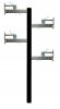
I have used what is on page 32 many times. The elements are driven in phase. The length of the coax is the same for each antenna piece. Or they could be 1 wave length different. In my applications each element is delayed by 1 wave length. I ran the coax up the tower and "T" out every wave length. Some antennas are "T" out at 3/4 wave length.
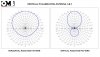
If you look at page 31, For a vertical antenna. The graphs on the left is seen from the top view. 0=north, 90=east, 180=s, 270=west. Page 34 shows power in all directions. If you look at your antenna it shows the south is 1/2 of north. South is the direction of your pole. So face the antenna toward the most people and the pole side the direction with the least people.
Page 31 left side graphs. Top graph; 0=up, 180=down, 90 & 180 is to the horizon. This is for 1 element with a gain of 1.
Page 31 left side graphs. Bottom graph; 0=up, 180=down, 90 & 180 is to the horizon. This is for 4 element with a gain of 4. The signal at 90 and 180 is 4x stronger. The signal at 120, through 180, is much much smaller and that is good. (4 elements 1,2,3,4 up/down the pole)

 ).
).