Continue to Site

Welcome to our site!

Electro Tech is an online community (with over 170,000 members) who enjoy talking about and building electronic circuits, projects and gadgets. To participate you need to register. Registration is free. Click here to register now.

  • Welcome to our site! Electro Tech is an online community (with over 170,000 members) who enjoy talking about and building electronic circuits, projects and gadgets. To participate you need to register. Registration is free. Click here to register now.

FM Transmitter

Status
Not open for further replies.

Burningmace

New Member
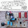
I wish to build a small FM transmitter. Nothing fancy, just something that'll transmit over a range of 20m or so with half-decent sound quality.

I found the following circuit on the net:
**broken link removed**

What I want to do is take off the electret microphone and replace it with a stereo audio jack. I've made some modifications that I think should work, but I may have got it completely wrong.
https://i29.tinypic.com/1z5j09w.gif

I'm no good with radio electronics, so I figured I'd ask here first.

The potentiometer is there so that I can adjust the pan, but it's not a necessary function. However, I do need to stipulate that I not interfere with other people listening to the radio in the house. Also, my dad has a decent transmitter (a few watts) that runs on 93.4MHz or something that he uses to listen to music around the house or in the garden or garage, and my transmitter mustn't interfere with his.

If you do suggest a replacement circuit or a modification, please make sure that it consists only of items I can buy from this electronics site, as I don't want to have to source other components elsewhere or start making my own coils out of spare wire.

Thanks in advance :)
 
A polite suggestion: Use Google to search previous postings on this forum. This subject has been beat to death here...
 
I did look, and I know it has been talked about a lot, but the circuits I have found are usually pretty complex in comparison with what I want. As I'm looking for something a simple and somewhat specific (i.e. no hand made coils, a way to connect it up to my PC, and stuff only from one site) I figured it would be best to create a new thread.
 
The coil isn't specified in your drawing. What coil do you propose to use?

There are lots of ways you can prevent interferring with other people's reception. The best way is just to find a quiet spot in the FM band to transmit on. Further, you have to limit the output power so that your neighbors cannot pick up your transmissions.

Every subject gets recycled here at some point. I can't even count how many threads are about lighting an LED, probably the most simple thing anyone will ever do in electronics.
 
Last edited:
Techie - Even if it is covered way too much, is it so hard just to give me some advice on the specific circuit I posted? Will it do the job?

BrownOut - No idea, I suck at FM electronics. Care to give a suggestion?
 
I for one don't mind new threads on old topics. The old ones on this subject get so long, and so many contributors and the S/N levels are rediculous. I don't have the patience for some of them. At least the OP came with something in mind. Every day, there are numerous posts that say, "I have no idea what to do. Please do it for me." That's the threads the annoy me.

Sorry, I don't have any suggestions. I'll look at the circuit later, I'm not sure about how the coil is connected. Something doesn't look right. Look at Audio Guru's transmitter. Those coils are correct, and winding isn't hard at all. Probably easier to wind than to find a suitable one.
 
Last edited:
PS: The center tap on that coil is superfulous, and might prevent the circuit from working. My guess is the author had a junk coil lying around with a center tap and connected it to the most convenient place, and somehow got the thing to work. If you can't find a suitable coil, either wind one or grab a handful from a busted radio and experiment.
 
Last edited:
Will 6 turns of PC molex cable wire around a standard sized pencil do the job? I figure I'll need to stretch it to be about an inch long.
 
The original schematic shows the antenna connected to +9V instead of to the tap on the coil.
I don't know why the OP is using input transformers.

The circuit will have extremely poor performance because is is too simple:
1) Its frequency will change if something moves near its antenna and as the battery voltage runs down.
2) This FM transmitter does not have pre-emphasis so it will sound muffled when played on an FM radio. Like your stereo with its treble tone control turned all the way down.
FM radio stations use pre-emphasis (treble frequencies boost) and all FM radios have a corresponding de-emphasis (treble frequencies cut) to reduce hiss but allow audio frequencies to be perfect.
3) Its value for C4 is so high that frequencies above about 1kHz will not be transmitted.
4) It is designed for a very low sensitivity microphone so its input will be severely overloaded by the signals from your PC.

I fixed an FM transmitter similar to this one:
1) I added an RF amplifier transistor at its output so that its antenna is not connected to the oscillator's tuned circuit and its frequency does not change when something moves near its antenna.
2) I added a low-dropout voltage regulator so that its frequency does not change as its battery voltage runs down.
3) I added pre-emphasis so that it sounds perfect when played on an FM radio.
But like this one it is mono, not stereo.

There is an excellent FM stereo transmitter kit in Australia called The Micromitter. It was featured as a project in Silicon Chip magazine about 5 years ago. It uses the same IC as most MP3 to car radio transmitters use.
 
Just buy an FM modulator designed for IPods, MP3 players, and such. They are cheap and likely will work a lot better than anything you will build, especially if you are not familiar with RF layout requirements.

To get FM stereo you need a stereo modulator circuit as part of the FM transmitter.
 
Thanks for the reply audioguru. Here's a few proposed modifications based on your suggestions:
1) Remove the joint to the +9V line on the antenna. I think this was a drawing error by the original designer.
2) Run a 7809 regulator from the +12V line on a molex inside my PC to power the cirucit.
3) Change C4 to a smaller value - will 5nF do the job?

The two things I'm not so sure on are the RF amp transistor on the on the output and the pre-emphasis. I've pretty much completely guessed with the transistor.

https://i32.tinypic.com/2gwys9k.gif

crutschow - I'm doing this because I enjoy these kinds of projects, not just the end result. Thanks though.
 
Last edited:
Hi Burningmace,
Your changes to the transmitter circuit will stop its oscillator from working.
the coil must be from the collector of the oscillator transistor to +9V and the RF amplifier must be capacitor-coupled to it and be biased with a resistor.

Here is my FM transmitter circuit:
 

Attachments

  • FM transmitter pic + schem.PNG
    FM transmitter pic + schem.PNG
    195.9 KB · Views: 3,094
If you want to transmit stereo you might build a kit such as this **broken link removed**.
 
If you want to transmit stereo you might build a kit such as this **broken link removed**.
It uses the horrible-performance obsolete BA1404 IC that was replaced 6 years ago with much better ICs.
 
audioguru - I did see that before and it looked too complex, but on a second look it's actually not as complex as I thought it was. Is there a simple way to remove the electret mic and replace it with my audio jack?

I've ordered the parts for the transmitter, plus a few extras I needed. I assume that using standard 33K instead of 30K on R3 and 33pF instead of 30pF for C12 shouldn't make a difference, as it's within tolerance of the components anyway.
 
Last edited:
Will 6 turns of PC molex cable wire around a standard sized pencil do the job? I figure I'll need to stretch it to be about an inch long.

No. You need magnetic wire. You can buy some online or scavage some from old transformers or coils. If I remember correctly, the coils are 9 - 11 turns with about 5/16" inside diameter. I don't recall a center tap, but you'll have to double check that.

I know from experience that the most critical part of getting an oscillator to osciallate is the Q of the network. The coil is usually the part that determines circuit Q. Use the correct wire and wind it correctly and you'll probably get good results. It's not all that hard really.
 
Last edited:
I believe my dad has some old coils in his parts cabient in the shed, but they're stored all together in one tray so I don't know what value they are. I'll see if he has any that are 9-11 turns and that are similar in dimensions to the ones you mentioned.

A pencil is roughly 8mm (5/16") in diameter so that should do if I want to wind one myself.
 
Last edited:
Just give it a try. Radio is all about experimentation. But double check in the antenna connection. It the transmitter works, you should be able to find a 'quiet' spot on a radio placed close to the transmitter. Tweak the tuning capacitor and verify that the quiet spot changes. Make sure you don't get reception more than a few meters away. You can use a shorter antenna or lower voltage to reduce the transmitted power. Both will change the transmitted freq. but you can just re-adjust that.

Keep all leads short as possible. Place connecting components close to keep interconnections short.

EDIT: I was looking again at your original circuit. I looks to me like the dot that depicts the antenna connection is misplaced. It should connect the center tap of the coil to the rail. That's a common way of coupling an antenna. If you don't have a center-tap coil, you might just try your circuit without an antenna. You mght get a signal with a receiver placed close to your circuit. If that works, then you can think about how you want to connect the antenna. You can always just wind a simple coil with a tap.
 
Last edited:
Here is my FM transmitter circuit:

Hi Audioragu,

I like the design of your FM transmitter. I can see the preemphasis cap is C4 and calculate its turnover frequency is ~2,260 Hz, depending on the tolerance of C4.

How do you generate the modulation? Does C7 have variable capacitance with voltage? If so, is it ceramic X7R or what type of cap did you use? I don't see any other components that could generate the modulation.

Bob
 
Status
Not open for further replies.

Latest threads

New Articles From Microcontroller Tips

Back
Top