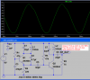
Your 'scope tries to show an audio signal. But the output of an FM transmitter is not an audio signal, instead it is a radio signal at a MUCH higher frequency.
You have a very high audio frequency of 10kHz which is boosted by the pre-emphasis made with C4. Then your XLV2 audio signal level must be about only 1mV.
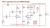
You are using the FM transmitter circuit I designed 14 years ago but I used a 9V battery for its design. You are using 12V which causes a much higher output power which is illegal without a transmitter licence. Also the circuit must be changed for using 12V so that the output does not produce distortion harmonics that interfere with important police, ambulance and fire dept. communications. If the RF cops catch you then you will be in big trouble.
Another problem you show is that your simulation is missing an important 75 ohms whip antenna.
Here is a simulation of the radio frequency from the radio parts of my transmitter: