Continue to Site

Welcome to our site!

Electro Tech is an online community (with over 170,000 members) who enjoy talking about and building electronic circuits, projects and gadgets. To participate you need to register. Registration is free. Click here to register now.

  • Welcome to our site! Electro Tech is an online community (with over 170,000 members) who enjoy talking about and building electronic circuits, projects and gadgets. To participate you need to register. Registration is free. Click here to register now.

FM TRANSMITTER WITHOUT A TRIMMER CAPACITOR

Status
Not open for further replies.

Metor

New Member
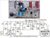
Good day genius. Please I have been working on a project now but had being handicapped because there is no trimmer capacitor (variable capacitor: 5pf-100pf) at my end. All attempt to secure some had failed. Please how can I build the FM transmitter with trimmer capacitors. Thanks
 
You can put a fixed capacitor in.
47pF will be about center. Do you have some small capacitors like 33p and 51p? Put one in and see what frequency you are on.
I can not see you coil or inductor. What does it look like? Can you change it?
 
I have 47pf, 22pf but not 33pf or 51pf. Do you have a working circuit of this. Thanks in anticipation
 
The trimmer capacitor probably sets the output radio frequency. My FM transmitter uses its 5pF-35pF trimmer capacitor C6 to adjust the radio frequency anywhere on the 88MHz to 108MHz FM broadcast band. Your trimmer goes as high as 100pF to go down to the 76MHz low frequency limit of the Japanese FM broadcast band. My trimmer C13 peaks the RF strength at the radio frequency you are using.

Why didn't you post the schematic of the circuit you are building? Here is mine that is built on stripboard and has a 5V low dropout voltage regulator so that the radio frequency does not change as the 9V battery voltage runs down:
 

Attachments

  • FM tx mod4 pic and schematic.jpg
    FM tx mod4 pic and schematic.jpg
    196 KB · Views: 471
Waow. This is a wonderful design. Like I said, I couldn't get the trimmer capacitor at my end. So I'm completely stranded.
 

Attachments

  • PROJECT 2.png
    PROJECT 2.png
    7.5 KB · Views: 346
completely stranded
Use any fixed cap you have and see what frequency you get.

If you need to move the frequency a little make a "gimmick capacitor" and add it in parallel with your capacitor. Search on the internet, it is made by two pieces of insulated wire.
 
By twisting a pair of wires, obviously keeping the plastic jacket in place, you could build quite quickly capacitors in the pF range.

Build one, measure it and try with a similar again. You get nice repeatability. You need a little less? just trim it but cutting the top end.
 
Use any fixed cap you have and see what frequency you get.

If you need to move the frequency a little make a "gimmick capacitor" and add it in parallel with your capacitor. Search on the internet, it is made by two pieces of insulated wire.
Thanks. I will give it a try
 
By twisting a pair of wires, obviously keeping the plastic jacket in place, you could build quite quickly capacitors in the pF range.

Build one, measure it and try with a similar again. You get nice repeatability. You need a little less? just trim it but cutting the top end.
Genius. Thanks
 
gimmick capacitor
GIMMIC CAPCITOR <----link
1555165705648.png

You can also change the frequency by changing the coil. This kind has a "slug" that turns and moves in/out to change the value.
1555165804372.png

Another way to change the frequency is to separate the wires a little in the coil. In the picture I tried to show pulling one turn out a little. If you bend one turn 90 degrees it is almost like removing it.
1555166019316.png
 
GIMMIC CAPCITOR <----link
View attachment 117667
You can also change the frequency by changing the coil. This kind has a "slug" that turns and moves in/out to change the value.
View attachment 117668
Another way to change the frequency is to separate the wires a little in the coil. In the picture I tried to show pulling one turn out a little. If you bend one turn 90 degrees it is almost like removing it.
View attachment 117669
Waow. Here is home. I'm learning a lot. Thanks
 
It is against the law to transmit a radio signal on public broadcast bands without a licence. If anybody complains of interference then the RF cops will arrest you and you will be in big trouble. My large city has many FM radio stations and other cities nearby have more so a vacant frequency is not available. I tested my FM transmitter for less than one hour using the frequency of a low power foreign language station and I was not caught.
 
Well noted. Will take that into consideration. Please take a look at this circuit for me. Thanks in anticipation
 

Attachments

  • 4-transistor-fm-transmitter project 3 .gif
    4-transistor-fm-transmitter project 3 .gif
    11 KB · Views: 344
Your new circuit has problems:
1) It is missing pre-emphasis (high audio frequencies boost) like all FM radio stations have so the sound received will be very muffled since all FM radios have de-emphasis (high audio frequencies cut).
2) Its RF oscillator is missing a voltage regulator so its radio frequency will change as the battery voltage runs down.
3) Its output coil is not tuned so it will transmit harmonics which will interfere with many other communications like ambulance and police radios use.

My FM transmitter circuit fixed these problems.
Thanks for checking it. Can you modify it for me?
 
Status
Not open for further replies.

Latest threads

New Articles From Microcontroller Tips

Back
Top