Continue to Site

Welcome to our site!

Electro Tech is an online community (with over 170,000 members) who enjoy talking about and building electronic circuits, projects and gadgets. To participate you need to register. Registration is free. Click here to register now.

  • Welcome to our site! Electro Tech is an online community (with over 170,000 members) who enjoy talking about and building electronic circuits, projects and gadgets. To participate you need to register. Registration is free. Click here to register now.

FM transmitter (mod4)

Status
Not open for further replies.
Most of your questions are answered (several times each, in most cases), in the previous 499 messages in this thread.
 
1 why c4 is different?
Because America was the first country to have FM radio stations then they decided to use a lot of pre-emphasis to reduce hiss. In those days microphones and recording equipment produced few high frequencies. Then later when Europe began using FM stations the microphones and recording equipment had more high frequencies and they decided to use less pre-emphasis so that there is less over-modulation. America kept their "mistake" and Europe used their different pre-emphasis.

2 how signal from q1 modulates oscillations due to q2 producing fm?
The audio signal from Q1 to the base of Q2 amplitude-modulates the base voltage of Q2. When the amplitude of the base voltage of Q2 is modulated then the changing voltage causes its capacitance to change. The changing capacitance changes the frequency of the oscillator which is FM. FM radios ignore the small amount of AM.

3 why regulator is used?
A 9V battery voltage drops to only 6V or less during its life.
Q1 works properly only when its supply is 5.0V.
If the supply to the oscillator changes then its frequency changes.
Cheap simple FM transmitter circuits without a voltage regulator have their frequency changing all over the place.

4 why q3 is used as colpitts oscillator again?
Q2 is a Colpitts oscillator circuit. Q3 is an RF amplifier and buffer so that the oscillator frequency does not change when something moves toward or away from the antenna. Other circuits are Hartley or many other types.

5 can we use other mic in place of electret in this circuit?
R1 powers the Jfet inside an electret mic. If R1 is removed then a dynamic mic (coil and magnet) can be used.

6 which are best books for analog electronics,digital electronics,communication systems and network analysis and synthesis?
I used books when I went to school and university 48 years ago. In the seventies I bought The TTL and The Cmos Cookbooks by Don Lancaster.The Art Of Electronics is a good book today.
 
Why are there 500 replies to this thread about this simple FM transmitter circuit?
It is mono, not stereo. My design is more than 5 years old.
 
thanks very much audioguru for all your assistance
actually i have made a temperature sensor using microcontoller
but now i want to make the sensor go wireless like sensor on transmitter circuit and dispay on the reciever side
ur transmitter has a good range . so i think it is possible to do it.
so sensor in place of microphone
value of r1 will be adjusted according to the voltage given to the sensor
c1 change according to the output current
no need for c4
and the rest of the circuit will be same
am i right

thanks
 
My FM transmitter has an AC input from a microphone.
But a temperature sensor has a DC output, not AC.

An FM radio has an AC output, not a DC output.
So your idea will not work unless the temperature sensor has an audio output frequency that changes when the temperature changes.

An FM radio has de-emphasis that reduces high audio frequencies. C4 in my circuit does the opposite so that all audio frequencies have the same output level.
 
i dont think so audioguru
maybe thermocouples give ac output .
but i want to use ic temperature sensor lm 35 series
so can i use an inverter which converts dc into ac of audio frequency
 
You can use an LM35 that has a DC outout that drives a VCO if you want. Then decode it at the FM receiver.
 
thanks audioguru
i just searched about about many types of VCOs
so i have to design vco which gives 88 to 108 MHz output frequency
but designing is very difficult for beginner like me
i also read about integrated circuit vco but they give pulsed output with 2 MHz maximum frequency 2 MHz which is very less than 88 to 108 MHz

so i cannot use vco directly by replacing colpitts oscillator
so can i use pulsed output as modulating signal at the base of q2
but i know fm is the modulation of oscillator signals by the amplitude of modulating signal but not the frquency
but pulsed output has constant amplitude at each cyle so i think frequency modulatio is not possible in the case of ic vco

so help me by giving me some tips /tutorials about how to design a vco with frequency 88.5 to 108.5 MHz

thanks
 
Rohm make some very good FM stereo transmitter ICs. They use a quartz crystal controlled frequency synthesizer with a phase-locked-loop and use some dip-switches to select a frequency. Most MP3 player to car radio transmitters use one.

Sorry, I don't know a VCO circuit that works near 100MHz and i don't know any tutorials.
 
you want to use the audio input of the FM modulator for the purpose, why do you need a VCO on FM range? your receiver will be tuned to only one frequency but the audio input can be from a low frequency VCO.
or you can think about coding the value to multiplexed tones as a digital bits.
 
you want to use the audio input of the FM modulator for the purpose, why do you need a VCO on FM range? your receiver will be tuned to only one frequency but the audio input can be from a low frequency VCO.
or you can think about coding the value to multiplexed tones as a digital bits.

actually i want to make a wireless temperature sensor whose input on transmitter side and display on reciever side
but sensor actually gives 1 mV to 1000 mV dc output so i have to use a vco in order to convert dc input into output frequency

many vco ic take that dc input and convert them into output frequency around 2 Mhz but square wave output
so problem is that square wave output could not be used for fm
so i want to directlry convert dc input intom fm frequency and send it to antenna
 
hello audioguru
can a varactor diode be added in your circuit for dc voltage

can you give me othe oscillator designs like hartley or othes which use varactor diode
 
Last edited:
You can add a varactor diode across the tuning inductor if you want.
There are hundreds of FM transmitter circuits on the internet. Some use a varactor diode for tuning and for FM modulation.
 
why don't you covert the out put to binary, depends on your accuracy you can make it to 8 or 16 bit data. then use two low frequency audio to represent the data, like scanning the data and switch between both audio sources as per the value of the byte and feed it to the modulator.( it will give you a serial data of two different tones like you play a piano to the microphone input of the transmitter using two keys only). scan it at a rate of 1 cycle/ sec or faster depends on the required scanning rate of your system. (there may be some limitations)

at the receiver end you have to decode the audio into a parallel data (reverse) and feed it to your display.
 
hello audioguru

i have made some modification in ur circuit with varactor diode and want to share it with you
but not able to attach the schematic file inthe post

so any solution
 
Last edited:
so finally i attach the image in my album
link is
**broken link removed**

so i made changes
plz correct me if i am wrong anywhere
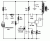
component numbers are differ in this image than urs image.
1 varactor is added in parallel with inductor
2 reverse voltage is applied across varactor and inductor 10 uH
3 10 uH is added so as to block oscillator signals to short into the ground
4 i think 10uH is sufficient to produce large impedence for oscillator signals?
5 as figure shows there is open between L1 and D1 but it not open but ther is a capacitor in between .this capacitor is added to prevent shorting of Q1 collector .am i right in doing all these?
6 let suppose this capacitor is c16 so c16,c1 and c varacotr are inseries and their is equivalent is parallel with L1 and C2
7 so L1,c2,c15,c16 determine the frequency of carrier oscillations and c varactor determines frequency deviation
8 Ceq=c1 series c16 series c varactor
9 c total=Ceq+c2
oscillation f=1/(2 pi sq root(c total*L1))
10 first transistor of ur circuit is not needed at this point so i start the circuit with r1 and c4?
11 i dont know whether c4 is required or not ?
12 rest of the circuit is same
13 in figure ,left topmost wire no included in figure is 5V regulated
14 wire applied across varactor is amplified output from sensor

plz correct me if i am wrong anywher
 
Your schematic is huge and has pastel lines on a dark grey cloth background so I can barely see it and I cannot correct it.

1) Remove L2.
2) Connect the anode of the varactor diode directly to the collector of Q1, not to its emitter.
3) Reduce the value of trimmer capacitor C2 by the capacitance of the varactor diode.
4) C4 causes the transistor to be a common-base oscillator and must be used.

Your circuit has the varactor diode biased oddly. It would be difficult to change its capacitance with voltage.

Varactor tuned FM transmitters have the varactor diode connected to ground so that a positive DC voltage can tune the radio frequency like this one:
 

Attachments

  • FM transmitter varactor.GIF
    FM transmitter varactor.GIF
    4.3 KB · Views: 395
1) Remove L2.
2) Connect the anode of the varactor diode directly to the collector of Q1, not to its emitter.
3) Reduce the value of trimmer capacitor C2 by the capacitance of the varactor diode.
4) C4 causes the transistor to be a common-base oscillator and must be used.

:

yes thanks
i saw transmitters with varactor diode
but still i want to experiment it on ur circuit
here again modification
will it work
Picture 1 of 3 from modified fm transmittor

sorry for blurred and enlarged image
i dont know how to convert schematic file into image file
so i am using my digital camera to take picture from schematic
 
Your schematic is much too big and the lines on iyt are almost the same color as the dark background so i cannot look at it.
Use a schematic drawing program.

I make schematics and copy parts of other schematics with Microsoft Paint program. Then I save it as a PNG file and attach the file to my reply here.

now my schematic is okay

ground connected to varactor diode is the ground of opamp connected to sensor
it is not the ground of actual circuit
i have done this so that collector of q2 doesnot short to the ground

Picture 1 of 4 from modified fm transmittor
 
Status
Not open for further replies.

Latest threads

Back
Top