Electro Tech is an online community (with over 170,000 members) who enjoy talking about and building electronic circuits, projects and gadgets. To participate you need to register. Registration is free. Click here to register now.
Welcome to our site! Electro Tech is an online community (with over 170,000 members) who enjoy talking about and building electronic circuits, projects and gadgets. To participate you need to register. Registration is free. Click here to register now.
A 2N2222A has different capacitance than a 2N3904 but should work. Try it.
But the frequency might not be in the FM broadcast band without changing the coils.
A 2N2222A has different capacitance than a 2N3904 but should work. Try it.
But the frequency might not be in the FM broadcast band without changing the coils.
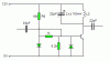
Q3 will operate in class-C if the 47k base resistor connects to ground instead of to +9V. I simulated it with a 12V supply and the output power became 0.09 times the power when it was the original circuit with a 9V supply.
Q3 will operate in class-C if the 47k base resistor connects to ground instead of to +9V. I simulated it with a 12V supply and the output power became 0.09 times the power when it was the original circuit with a 9V supply.
that what I was thinking, so input is where the aerial is. and can the output be a 70cm long of wire (aerial) or should I connect a cap in series with it? I must construct it on vero board and keep leads as short as I could. then should I place every thing I a box and cover it with foil that is connected to the ground of the power input? and can I just use regulated 12V for the amplifier (it is 15V on the schematics)?
and for the 0.82uH and the 0.47uH inductor, do you use homemade aircore inductors. using the aircore inductor formula?
LTSpice?
I've got MultiSim 10 and proteus 7
and I also run a coil calculator I got from the internet. It shows that the coil shown on the first page. the one with 9 turns, 5mm diameter and 10.16mm length has got a inductance of 0.23uH. Should I use that coil, or wind my own one that has got 0.1uH of inductance as specified on the diagram.
These are from the LC equation, I dont know if it is correct or not, since as audioguru said that the stray capacitance got a huge influence on the behavior of the circuit.
This site uses cookies to help personalise content, tailor your experience and to keep you logged in if you register.
By continuing to use this site, you are consenting to our use of cookies.