Electro Tech is an online community (with over 170,000 members) who enjoy talking about and building electronic circuits, projects and gadgets. To participate you need to register. Registration is free. Click here to register now.
Welcome to our site! Electro Tech is an online community (with over 170,000 members) who enjoy talking about and building electronic circuits, projects and gadgets. To participate you need to register. Registration is free. Click here to register now.
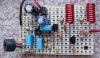
The photo shows it on a piece of stripboard that measures only 1.3" x 2.0" and has corners for mounting bolts.
Count the holes that are 0.1" apart.
I was lucky to find tiny trimmer capacitors.
One extra resistor (560) is on top but not connected to an LED.
The 47k resistor is on the bottom.
audioguru,
Could you please put labels linking each component on your board to the schematic on the photograph. I can guess most of them but it might help the noobs more.
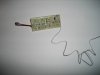
Two yellow wires connect the jack to the board...the other 3 connect the power section to the other parts. Well if 7805 is a noisy LDO what can i use instead of that and LM2931 (i have LM340). Also i noticed that the transistor connected to the 2nd coil gets quickly heated when a current passes through it.
Something is wrong with the layout of your circuit to cause the output level of the oscillator to be low. Then the output transistor gets too hot.
Try using a 10pF capacitor as feedback in the oscillator instead of the 4.7pF for C7 shown on the schematic.
I finished reading the thread, I will be building one soon, do you think it can cover a building, which is about 150m radius from the point of transmission?
BTW that guy who can't find the new thread button, hahahahahahahahahahahahahahaha. shame man.
If the building is made with rice paper and bamboo then the transmitter will cover it if the radios are a high quality.
But a reinforced concrete or steel building will have poor coverage.
Ok, the receivers are all cellphone fm radio and good hi-fi's. etc.
But I'd love to have it running on a 12V lead acid battery. Do I just add a 7809 regulator or maybe leave it alone and replace Q3 with something thats a bit bigger?
Can I use this as a power supply?
the Input is a wall adapter, maximum current 500mA, has a built in bridge rectifier and a 1000uF filtering capacitor.
Its the 12V output fine? or must I rather stick to 9V?
This site uses cookies to help personalise content, tailor your experience and to keep you logged in if you register.
By continuing to use this site, you are consenting to our use of cookies.