Continue to Site

Welcome to our site!

Electro Tech is an online community (with over 170,000 members) who enjoy talking about and building electronic circuits, projects and gadgets. To participate you need to register. Registration is free. Click here to register now.

  • Welcome to our site! Electro Tech is an online community (with over 170,000 members) who enjoy talking about and building electronic circuits, projects and gadgets. To participate you need to register. Registration is free. Click here to register now.

flying probe test

Status
Not open for further replies.

Naoum

New Member
Hi,
I am an engineer student and I wish build a flying probe test for PCB (with two probes).
I have a python file that contains the positions of the components on the PCB.
I don't know what kind of stepper motors that should I use and how can I control them with arduino /python .
Any help please
thanks.
 
There are many examples on the internet of using computers to run CNC routes, 3-D printers, milling machines, etc.
I think there are open source programs for all this. (very much related to flying probes)
There are kits with motors and rails.
Read up on the may ways of moving a head with motors.
Because you probes are small (light weight) I think you can use very low power motors.
I think a 3-D printer is a good place to start.
 
Hi Ronsimpson,
I found many articles about CNC machine et 3D printer but they 're based on G-code and gerber shield that I hadn't.
I juste had a pcb layout (.CAD file) that I export from it a liste that contains the position of the components with Python.
Now I don't know how do I explote this data to command the stepper motors (and probes' moving) with an arduino .
 
I think you should start with the mechanics, make it so that the two probes won´t crash into each other. Then you need to calculate the X and Y of each probe and command the motors to move the probes, then stick them into the pcb.
 
Hi, exploiting adruino and steppers depends on configuration placement of steppers, a 3d printer firmware for each type should have examples you can cut out,

here is link to my printers adruino firmware, note it is in a delta configuration, makes the calculation too complicated for me:
https://drive.google.com/open?id=0B...dVNWhxRFhtYWtLYmhPVkhZOWxMbGNGckc4VTA4Z0tfSkU

with 2 probes though you may need custom design since you will want the probes to be able to move freely in the bed without collisions. Some 3d printers can use 2 heads , but not with independent positioning at the same time, like you require

my 3d printer has serial terminal to send instructions where i can input specific codes, when printer is running print , it just pushes one G code line after another,
this is exactly what each instruction looks like:
G1 x2 y3 z4 e400 // g1 is the instruction to move, xyz are just the coordinates to move to, e is how much filament it pushes out

that is the only code really required to move the head around, also may want to incorporate other instructions such as g28(home) and G29(calibrate) , depending on your complexity you may need few more instructions.

even a robot arm style could be used, again need to watch out for collisions,
speed you have no need to worry about that, 3d printers do, but you would need to make sure your device has accuracy between steps.
 
mechanic solution
**broken link removed**
They have many mechanical parts.

I am thinking about your two probe problem. I think this is hard.
I would build a "two finger hand". Two fingers = two probes.
Using parts form robot shops on line.
Program the hand:
1) set the distance between probe1 and probe2, The fingers move to 0.5 apart.
2)rotate the hand, set rotation to 90 degrees.
3)Move the hand to over the part.
4)move hand down.

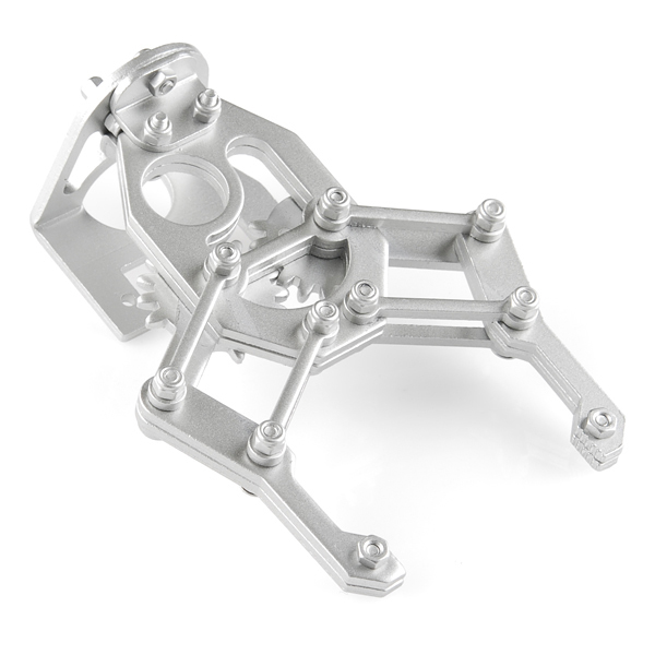
From sparkfun.com Here is a two finger hand. Think of a probe on each finger.
11524-01a.jpg


How much are those? I have been making mine but they take ages.
 
I have been making mine but they take ages.
Servo city no longer has these. I have seen several different types. I like the (one servo) hand type. simple.

https://www.sparkfun.com/products/retired/11524
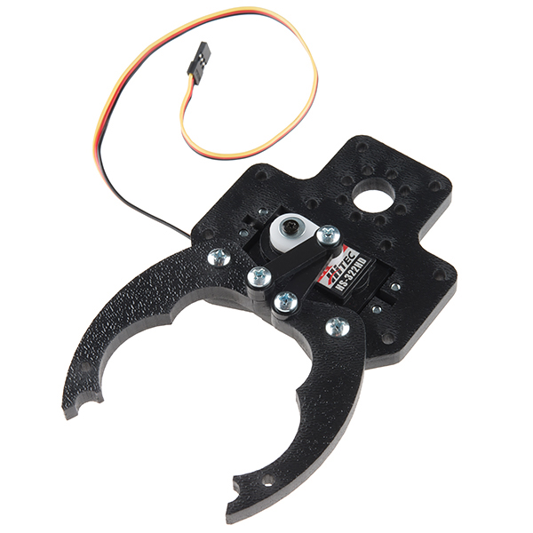
Spaarkfun.com does not have BUT They have a $6.00 and $10.00usd mini hand.
https://www.sparkfun.com/products/13174
Actobotics-105.jpg

**broken link removed**
---edited---
https://www.creatroninc.com/product/robotic-claw-mkii/
Found it $18.
https://www.spikenzielabs.com/Catalog/index.php?main_page=product_info&products_id=732
$12
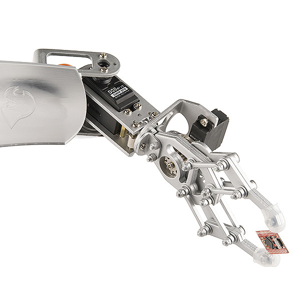
https://www.spikenzielabs.com/Catalog/index.php?main_page=product_info&cPath=22_95&products_id=1078
ROB-11674_LRG.jpg
 
Last edited:
Thats a good price! they take 3 days too make on the cnc.
 
Status
Not open for further replies.

Latest threads

New Articles From Microcontroller Tips

Back
Top