Continue to Site

Welcome to our site!

Electro Tech is an online community (with over 170,000 members) who enjoy talking about and building electronic circuits, projects and gadgets. To participate you need to register. Registration is free. Click here to register now.

  • Welcome to our site! Electro Tech is an online community (with over 170,000 members) who enjoy talking about and building electronic circuits, projects and gadgets. To participate you need to register. Registration is free. Click here to register now.

Flickering mute illumination LED on 4 yr old McIntosh Preamp

Status
Not open for further replies.
A loose connection/bad solder joint seem the most likely. The one joint looks suspicious even though the picture isn't great. It's hard to take a macro picture even with a MACRO lens and good lighting.

EDIT: This https://www.jst.co.uk/productSeries.php?pid=121&cat=22 could be the connector. Looks like the cable inserts easy and is hard to get out. A shim might help. e.g. https://www.mcmaster.com/shim-stock/shim-stock-6/
These feeler gauge sets were available in automotive stores or Sears when they were alive. https://www.mcmaster.com/feeler-gauges/economy-feeler-gauge-sets/

Some things I just measured (thousanths, mills, 0.001"

index card, 7
Clear cover (staples), 7
Blue plastic cover (staples), 10
manila folder, 10
Business card, 28 (I'm sure it varies)
Credit card, 30 (they probably vary too
lamintate (clear to clear (staples), 6
laminate both sides with paper, 13 (would depend on the paper thickness) e.g. 18, 22, 24 lb, card stock

It might help removal of the ribbon cable. I don't know,
 
Last edited:
I have ordered the LED bulb from McIntosh but I cracked the glass cover/faceplate so I had to order that as well. Do you have any idea how to remove the non-electrically switch that are on the faceplate-see pic?
 

Attachments

  • faceplate.jpg
    faceplate.jpg
    179.5 KB · Views: 196
The water is getting warm, huh?

I don;t recognize the switch. What I would have done is ordered one for the purpose of playing with it. You might just get that AhHa moment.

Aside:
I just ran into that with a toothbrush. This toothbrush will likely be sacrificial. The battery wasn;t an exact replacement. No polarity markings on the PCB or battery. Just the extended tab. I put a polarity marking on the PCB. If it was an OEM battery, it would have fit one way, I installed it backwards. It briefly make noise. I messed up the charging coil.

Any identifying markings would help.

here https://www.idec.com/language/english/catalog/Switches/SwitchFamily.pdf#page=18 is an example where it isn't obvious and care is expected.

In many cases the actuator, lighting and contact blocks are separate.
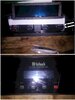
This
1609358486511.png


is one such similar animal I worked with until Iused about 200+ of them. It was a nice design until "they" redesigned the lens. It was cool because the switches (black section) could be removed, but not purchased
separately, The middle area was reserved for the lamp and the other side contained an optional switch.
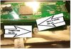
They are NO NC switches, not SPDT. it could be wired with 0.110" fastons or solder.

You pushed the yellow writing in on both sides to release the contact block.

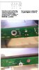
The front panel sits between the square metal thing with "dig in tabs". here, the contact block is removed and it's installed from the front. A special tool tightens the castle like nut. It goes together easier that taken apart.

It's very likely, it has to be disconnected/tightened to the panel in the back.
 
Last edited:
Since I broke my screen right across one of the switch's I was able to pull it out and it has a rubber o-ring that fits in a grove to hold it in place. You would use a pick to roll it out of the grove and then pull it forward from the panel. it did have something they used to hold the circuit board to the switch which looks almost like a glue gun but it was stronger than a glue gun and solid white. i had to use a hair dryer to heat it up to peel it off. Have any idea what that is?
 
try this first before soldering or sending the board out... get a can of "canned air" and a small brush with steel bristles. around the perimeter of the controller chip, use the brush, starting at the edge of the epoxy body of the chip and brush away from the chip in the same direction the pins go... do this carefully, you don't want to damage the pins or the solder mask. once done, spray canned air at the center of the chip to blow away any metal flakes that might be near it. it's likely after 4 years there may be tin whiskers growing between the pins of the chip, and might be part or all of the LED problem, since the LED is driven by an output on the chip.
 
How about something like this? https://www.amazon.com/dp/B07PG9X9L8/ref=twister_B07PJLB5CR?_encoding=UTF8&psc=1
It looks like it really has no "electronic" use in the true sense. It is used to hold the small circuit board to on the 4 switches to hold/adhere them together. The switches have plastic clips/arms to hold this together but I can see in time this could work loose so it appears that McIntosh used this method to prevent this from happening in the future.
 
OK It looks like I have been chasing the wrong culprit. The LED bulb that sticks out only illuminates when the Mute button is pressed. The culprit that is actually causing the issue is something recessed in the board. See pic. Is that an LED inside the board??
 

Attachments

  • BOARD2.jpg
    BOARD2.jpg
    169.7 KB · Views: 184
I can't make any sense out of the second lower picture above.

The LEDs tied to a resistor likely go to power unless there is a dimming circuit.

It appears that you illuminate the button or around the button and then illuminate the function. i.e. When mute is activated, that LED is on. When power is on, The mute button probably has an aura around it all the time.

"REV MNT" suggests the solder pads are on the other side of the board. Without real part numbers, it's hard to tell.
 
The pic shows both sides of the board for the mute button light (which is the bulb that sticks out of the board) and the mute button illumination light which is the one that looks like it is a part of the board (this is the one that flickers) & is referred to as DS9 in the service manual and also on the board. Considering the circuit for DS9 in the service manual what chance do you think that this is an issue with the board as I cannot see a way to replace that LED as it is recessed into the board? Let me know what you think also are those LED replaceable when they are recessed in the board like this one?
 
Interesting blurb: https://hackaday.com/2019/04/17/the-science-of-reverse-mounted-leds/

i have never seen them before. e.g. https://www.farnell.com/datasheets/2711909.pdf

There looks like a gap in R43 at the bottom in the pic in post #33. Too much heat while not holding R43 down and it will float away. I don't think it's the LED joint.
I wonder if I should just get a new board made by McIntosh but how can I be sure that this will solve the issue. It looks to me like all the LED's for illumination are on the same circuit so if there was an issue with something outside the board or the actual LED itself all LED's for illumnation would share the same issue. What are your thoughts on that?
 
I wonder if I should just get a new board made by McIntosh but how can I be sure that this will solve the issue. It looks to me like all the LED's for illumination are on the same circuit so if there was an issue with something outside the board or the actual LED itself all LED's for illumnation would share the same issue. What are your thoughts on that?
If it is just one LED flickering and there are four others, each with their own resistor, but all powered by the same supply, it's really got to be that one LED or its resistor, or the connections between those.
 
Status
Not open for further replies.

Latest threads

New Articles From Microcontroller Tips

Back
Top