Hello,
I am starting this thread on behalf of another member who is currently studying these topics.
We will start with a simple low pass filter using an op amp and possibly move on to other more complicated circuits. We'll be doing a full analysis finding the response and other interesting things about filters including cut off frequency.
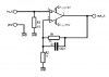
The first LOW PASS filter is this one:
We can generalize the circuit by naming the feedback network impedance Z2 and input network impedance Z1:
where
Z1 is the input resistor R1, and
Z2 is the parallel combination of the impedance of C2 and the the impedance of R2.
The impedance of R2 is simply R2, and the impedance of C2 is:
zC2=1/(j*w*C2)
where
w is the angular frequency equal to 2*pi*f, and
j is the imaginary operator where j^2=-1.
And also since if we multiply the top and bottom of zC2 by j we get:
zC2=j/(j*j*w*C2)
which simplifies to:
zC2=-j/(w*C2)
To put any two impedances in parallel, we use:
Zp=Za*Zb/(Za+Zb)
In this case we want to compute Z2 so we use Za=R2 and Zb=zC2, so we have:
Zp=R2*zC2/(R2+zC2)
which comes out to:
Zp=R2*(-j/(w*C2))/(R2-j/(w*C2))
So now we know what Z2 is:
Z2=Zp=-(R2*j/(w*C2))/(R2-j/(w*C2))
Now because the non inverting terminal is connected to ground we can solve the circuit
quite easily knowing Z1 and Z2, but instead lets be a bit more general and use
superposition.
Since we know the input is Vin and the output is Vout, lets first short Vin and solve for
the voltage at the inverting terminal:
vn1=Vout*Z1/(Z1+Z2)
and again with Vout shorted and Vin not shorted solve for the voltage at the inverting terminal:
vn2=Vin*Z2/(Z1+Z2)
and now the total voltage at the inverting terminal vn is:
vn=vn1+vn2
or
vn=Vout*Z1/(Z1+Z2)+Vin*Z2/(Z1+Z2)
and since this is connected to the inverting terminal it gets subtracted from zero and amplified
by the internal gain of the op amp we'll call Aol, so we have implicitly:
Vout=(0-vn)*Aol=Aol*(-(Vin*Z2)/(Z2+Z1)-(Vout*Z1)/(Z2+Z1))
Now we solve for Vout explicitly:
Vout=Aol*(-(Vin*Z2)/(Z2+Z1)-(Vout*Z1)/(Z2+Z1))
Vout=-(Aol*Vin*Z2)/(Z2+Z1)-(Aol*Vout*Z1)/(Z2+Z1)
Vout+(Aol*Vout*Z1)/(Z2+Z1)=-(Aol*Vin*Z2)/(Z2+Z1)
Vout*(Z2+Aol*Z1+Z1)/(Z2+Z1)=-(Aol*Vin*Z2)/(Z2+Z1)
Vout*(Z2+Aol*Z1+Z1)=-(Aol*Vin*Z2)
Vout=-(Aol*Vin*Z2)/(Z2+Aol*Z1+Z1)
and since Aol is considered very high, we take the limit as Aol goes to infinity and get:
Vout=-Vin*Z2/Z1
and the amplitude is:
|Vout|=-|Vin|*sqrt(RZ2^2+IZ2^2)/sqrt(RZ1^2+IZ1^2)
where
RZ2 is the real part of Z2, and IZ2 is the imag part of Z2, and
RZ1 is the real part of Z1, and IZ1 is the imag part of Z1.
This means we only have to know the real and imaginary parts of Z1 and Z2 to get the
amplitude response, and notice that if we divide both sides by Vin we get:
|Vout/Vin|=-|Z2|/|Z1|=-sqrt(RZ2^2+IZ2^2)/sqrt(RZ1^2+IZ1^2)
So it turns out that the amplitude transfer function is just the negative of the feedback network impedance
amplitude divided by the input network impedance amplitude.
Since we know what Z1 and Z2 are:
Z1=R1
Z2=-(R2*j/(w*C2))/(R2-j/(w*C2))
all we have left to do is divide Z2 by Z1 and then multiply by -1.
It helps here to simplify Z2 a little...
multiply top and bottom by w*C2:
-R2*j/(w*C2*R2-j)
multiply top and bottom by the conjugate of the bottom (which is w*C2*R2+j):
-R2*j*(w*C2*R2+j)/((w*C2*R2-j)*(w*C2*R2+j))
and simplify the top and the bottom separately:
(-w*C2*R2^2*j-R2*j^2)/(w*C2*R2)^2-j^2)
and since j^2=-1 we simplify more:
(-w*C2*R2^2*j+R2)/(w*C2*R2)^2+1)
so we have Z2 simplified now:
Z2=(-w*C2*R2^2*j+R2)/(w*C2*R2)^2+1)
and now we divide by R1 and get:
Z2/Z1=((-w*C2*R2^2*j+R2)/(w*C2*R2)^2+1))/R1
Z2/Z1=(-w*C2*R2^2*j+R2)/(R1*(w*C2*R2)^2+R1)
and multiply by -1 and get:
-Z2/Z1=(w*C2*R2^2*j-R2)/(R1*(w*C2*R2)^2+R1)
and then noting that the numerator is:
N=(w*C2*R2^2*j-R2)
and the denominator is:
D=(w*C2*R1*R2)^2+R1
we have:
|Vout|=-|Vin|*sqrt(RN^2+IN^2)/sqrt(RD^2+ID^2)
where RN is the real part of the numerator and IN is the imaginary part of the numerator and
RD is the real part of the denominator and ID is the imaginary part of the denominator.
So separating the real and imag parts in the numerator we get:
RN=-R2
IN=w*C2*R2^2
and in the denominator we have:
RD=R1*(w*C2*R2)^2+R1
IN=0
so the final response is:
|Vout|=sqrt((-R2)^2+(w*C2*R2^2)^2)/(R1*(w*C2*R2)^2)+R1)
noting that the square of the square root of RD^2+0^2 is just RD, and that comes out to:
|Vout|=sqrt(w^2*C2^2*R2^4+R2^2)/(R1*(w^2*C2^2*R2^2+1))
or:
|Vout|=(sqrt(w^2*C2^2*R2^2+1)*(R2))/(R1*(w^2*C2^2*R2^2+1))
which simplifies to:
|Vout|=R2/(R1*sqrt(w^2*C2^2*R2^2+1))
and that is the output response.
To summarize, the response because the non inverting terminal is connected to ground is:
|Vout/Vin|=-|Z2|/|Z1|=-sqrt(RZ2^2+IZ2^2)/sqrt(RZ1^2+IZ1^2)
where
RZ1 is real part of Z1,
IZ1 is imag part of Z1,
RZ2 is real part of Z2,
IZ2 is imag part of Z2.
I highly recommend following this throughout rather than skipping to the end and using the formula
because other more complex circuit will require a little more work. Here we assumed that the
non inverting terminal was connected to ground but that's certainly not always the case. When the
non inverting terminal is not connected to ground we have to do a more full analysis.
I am starting this thread on behalf of another member who is currently studying these topics.
We will start with a simple low pass filter using an op amp and possibly move on to other more complicated circuits. We'll be doing a full analysis finding the response and other interesting things about filters including cut off frequency.
The first LOW PASS filter is this one:
Code:
The circuit is a low pass filter:


               +---------R2--------------+
               |                         |
               +---------C2--------------+
               |               |\        |
               |               | \       |
               |               |  \      |
Vin o----R1----+---------------|-  \     |
                               |    +----+-----o Vout
                            +--|+  /
                            |  |  /
                            |  | /
                            |  |/
                            |
                            |
                            |
                            |
GND o-----------------------+------------------o GND
We can generalize the circuit by naming the feedback network impedance Z2 and input network impedance Z1:
Code:
Generalized with impedance networks Z1 and Z2:

               +--------Z2---------------+
               |               |\        |
               |               | \       |
               |               |  \      |
Vin o----Z1----+---------------|-  \     |
                               |    +----+----o Vout
                            +--|+  /
                            |  |  /
                            |  | /
                            |  |/
                            |
                            |
                            |
                            |
    o-----------------------+-----------------o
where
Z1 is the input resistor R1, and
Z2 is the parallel combination of the impedance of C2 and the the impedance of R2.
The impedance of R2 is simply R2, and the impedance of C2 is:
zC2=1/(j*w*C2)
where
w is the angular frequency equal to 2*pi*f, and
j is the imaginary operator where j^2=-1.
And also since if we multiply the top and bottom of zC2 by j we get:
zC2=j/(j*j*w*C2)
which simplifies to:
zC2=-j/(w*C2)
To put any two impedances in parallel, we use:
Zp=Za*Zb/(Za+Zb)
In this case we want to compute Z2 so we use Za=R2 and Zb=zC2, so we have:
Zp=R2*zC2/(R2+zC2)
which comes out to:
Zp=R2*(-j/(w*C2))/(R2-j/(w*C2))
So now we know what Z2 is:
Z2=Zp=-(R2*j/(w*C2))/(R2-j/(w*C2))
Now because the non inverting terminal is connected to ground we can solve the circuit
quite easily knowing Z1 and Z2, but instead lets be a bit more general and use
superposition.
Since we know the input is Vin and the output is Vout, lets first short Vin and solve for
the voltage at the inverting terminal:
vn1=Vout*Z1/(Z1+Z2)
and again with Vout shorted and Vin not shorted solve for the voltage at the inverting terminal:
vn2=Vin*Z2/(Z1+Z2)
and now the total voltage at the inverting terminal vn is:
vn=vn1+vn2
or
vn=Vout*Z1/(Z1+Z2)+Vin*Z2/(Z1+Z2)
and since this is connected to the inverting terminal it gets subtracted from zero and amplified
by the internal gain of the op amp we'll call Aol, so we have implicitly:
Vout=(0-vn)*Aol=Aol*(-(Vin*Z2)/(Z2+Z1)-(Vout*Z1)/(Z2+Z1))
Now we solve for Vout explicitly:
Vout=Aol*(-(Vin*Z2)/(Z2+Z1)-(Vout*Z1)/(Z2+Z1))
Vout=-(Aol*Vin*Z2)/(Z2+Z1)-(Aol*Vout*Z1)/(Z2+Z1)
Vout+(Aol*Vout*Z1)/(Z2+Z1)=-(Aol*Vin*Z2)/(Z2+Z1)
Vout*(Z2+Aol*Z1+Z1)/(Z2+Z1)=-(Aol*Vin*Z2)/(Z2+Z1)
Vout*(Z2+Aol*Z1+Z1)=-(Aol*Vin*Z2)
Vout=-(Aol*Vin*Z2)/(Z2+Aol*Z1+Z1)
and since Aol is considered very high, we take the limit as Aol goes to infinity and get:
Vout=-Vin*Z2/Z1
and the amplitude is:
|Vout|=-|Vin|*sqrt(RZ2^2+IZ2^2)/sqrt(RZ1^2+IZ1^2)
where
RZ2 is the real part of Z2, and IZ2 is the imag part of Z2, and
RZ1 is the real part of Z1, and IZ1 is the imag part of Z1.
This means we only have to know the real and imaginary parts of Z1 and Z2 to get the
amplitude response, and notice that if we divide both sides by Vin we get:
|Vout/Vin|=-|Z2|/|Z1|=-sqrt(RZ2^2+IZ2^2)/sqrt(RZ1^2+IZ1^2)
So it turns out that the amplitude transfer function is just the negative of the feedback network impedance
amplitude divided by the input network impedance amplitude.
Since we know what Z1 and Z2 are:
Z1=R1
Z2=-(R2*j/(w*C2))/(R2-j/(w*C2))
all we have left to do is divide Z2 by Z1 and then multiply by -1.
It helps here to simplify Z2 a little...
multiply top and bottom by w*C2:
-R2*j/(w*C2*R2-j)
multiply top and bottom by the conjugate of the bottom (which is w*C2*R2+j):
-R2*j*(w*C2*R2+j)/((w*C2*R2-j)*(w*C2*R2+j))
and simplify the top and the bottom separately:
(-w*C2*R2^2*j-R2*j^2)/(w*C2*R2)^2-j^2)
and since j^2=-1 we simplify more:
(-w*C2*R2^2*j+R2)/(w*C2*R2)^2+1)
so we have Z2 simplified now:
Z2=(-w*C2*R2^2*j+R2)/(w*C2*R2)^2+1)
and now we divide by R1 and get:
Z2/Z1=((-w*C2*R2^2*j+R2)/(w*C2*R2)^2+1))/R1
Z2/Z1=(-w*C2*R2^2*j+R2)/(R1*(w*C2*R2)^2+R1)
and multiply by -1 and get:
-Z2/Z1=(w*C2*R2^2*j-R2)/(R1*(w*C2*R2)^2+R1)
and then noting that the numerator is:
N=(w*C2*R2^2*j-R2)
and the denominator is:
D=(w*C2*R1*R2)^2+R1
we have:
|Vout|=-|Vin|*sqrt(RN^2+IN^2)/sqrt(RD^2+ID^2)
where RN is the real part of the numerator and IN is the imaginary part of the numerator and
RD is the real part of the denominator and ID is the imaginary part of the denominator.
So separating the real and imag parts in the numerator we get:
RN=-R2
IN=w*C2*R2^2
and in the denominator we have:
RD=R1*(w*C2*R2)^2+R1
IN=0
so the final response is:
|Vout|=sqrt((-R2)^2+(w*C2*R2^2)^2)/(R1*(w*C2*R2)^2)+R1)
noting that the square of the square root of RD^2+0^2 is just RD, and that comes out to:
|Vout|=sqrt(w^2*C2^2*R2^4+R2^2)/(R1*(w^2*C2^2*R2^2+1))
or:
|Vout|=(sqrt(w^2*C2^2*R2^2+1)*(R2))/(R1*(w^2*C2^2*R2^2+1))
which simplifies to:
|Vout|=R2/(R1*sqrt(w^2*C2^2*R2^2+1))
and that is the output response.
To summarize, the response because the non inverting terminal is connected to ground is:
|Vout/Vin|=-|Z2|/|Z1|=-sqrt(RZ2^2+IZ2^2)/sqrt(RZ1^2+IZ1^2)
where
RZ1 is real part of Z1,
IZ1 is imag part of Z1,
RZ2 is real part of Z2,
IZ2 is imag part of Z2.
I highly recommend following this throughout rather than skipping to the end and using the formula
because other more complex circuit will require a little more work. Here we assumed that the
non inverting terminal was connected to ground but that's certainly not always the case. When the
non inverting terminal is not connected to ground we have to do a more full analysis.
Last edited:
")
 . At least I know now to be careful not to do again :-D.