Continue to Site

Welcome to our site!

Electro Tech is an online community (with over 170,000 members) who enjoy talking about and building electronic circuits, projects and gadgets. To participate you need to register. Registration is free. Click here to register now.

  • Welcome to our site! Electro Tech is an online community (with over 170,000 members) who enjoy talking about and building electronic circuits, projects and gadgets. To participate you need to register. Registration is free. Click here to register now.

Filter for voice comms??

Status
Not open for further replies.
Hi Electricman,
Your original IR tx circuit didn't put much current through the IR LED because the output of a 555 is rated for only 200mA, and I don't know if your supply decoupling cap was suitable to provide that much current.
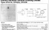
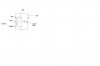
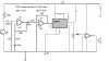
Now you are trying to use this complicated Mosfet circuit that uses the transistor and zener diode solely to convert the 5V output of its 555 to the 9V required by the gate of the Mosfet. If the 555 was powered from the same supply voltage as the LED/Mosfet, then the transistor and zener diode wouldn't be needed, just the 555 driving a P-channel Mosfet instead. Just about like your B circuit except using a 10A LED, no current limiting resistor and an extremely short-duration pulse.
You don't post where you are, so i don't know if you buy European BDxxx power transistors or American TIPxxx ones.

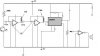
Your photodiode is upside down, it needs to be reverse-biased and the IR radiation causes it to have a leakage current. A diode doesn't have the gain of a transistor so the amplifier would need to have much more gain. Try reducing the value of the amplifier's 1K resistor or shorting it for plenty of gain.
 
P channel FET

Hi regarding the P-channel FET, i live in the UK so I think the BD series stc is more prominent, can you recommend a device. Im not sure what you mean regarding the decoupling capacitor and how relates to supply current, I thought they were there for noise immunity issues?.
 
Hi Electricman,
The Mosfet circuit will fry ordinary IR LEDs. Can you get that 10A IR LED in the UK? An ordinary PNP power transistor will work the same as a P-channel Mosfet in this application. Sorry, I don't know the BDxxx parts.

Since you are using 9V I assumed it was from a little 9V battery that can't provide much current. A supply decoupling cap stores a charge and supplies a high current on demand, as well as filtering. Its value must be enough so that it doesn't discharge too much during each IR pulse.
 
LED/PNP transistor

Hi I have the LEd in question it is the OPTEK 293W type I have attatched a segment of its data sheet. As far as the power PNP transistor, I have had a look at a few; some seem to have high values of Vce (this is the voltage drop across it right?) Some have values are like 4V this will leave only 9-4 =5V not to mention less 2V dropped from the LEd!!

I found a device with max current rating of 10A and Vce of about 1.5V it is D45H8 made by ON, Fairchild and Motorola. Its datasheet is below, from Fairchild I believe it says 8A Max, although ON and Motorola say 10A- it seems like a good bet anyway

**broken link removed**

Do you think its Ok?

Thanks
 

Attachments

  • led_165.jpg
    led_165.jpg
    101.6 KB · Views: 476
What power supply are you going to use to provide 10A pulses?

That PNP power transistor saturates well with a base current of 500mA and a collector current of 10A. Where are 500mA drive pulses going to come from?

The IR LED is rated for a maximum continuous current of 100mA. If you cram 10A pulses into it the duty-cycle must be about 1 to 100. At 38KHz its on-time will be only 0.26us. Your IR receiver and PLL won't see or hear pulses so short. Forget it.
 
The BD138 and just about any other medium power PNP transistor will work.
The range is also determined by the sensitivity and gain of the receiver. Will your receiver's photodetector and phase-locked-loop IC work with pulses having a short duty-cycle?
I think your transmitter needs a few IR LEDs in an array, with nearly 50-50 duty-cycle, and lotsa sensitivity and gain in your receiver.
 
pnp/npn/duty cylce

Hi I simulated the design below in a very basic tool(with 1 LED), using a PNP as T1 the square (ish!!) wave from my 555 output on the PNP emitter becomes more like a spike, the NPN transistor seems to reproduce it OK- it could be wrong, I was not using power transistors, so I had to decrease the voltage to say 5V.

Anyway I wanted to create a more even square wave using this tool

**broken link removed**

At 40Khz using 55% duty cycle can use r1=1.6k,r2=7.3k,c=2.2nf, the pulses are on/off for 13/11us - it says mark space is 1:1- Im using pin 5 control voltage to modulate the frequency does this change the mark space ratio?
 
Hi Electricman,
Your calculations are correct, but only if you don't have a frequency-adjusting pot, because it adds to the value of R1.
You shouldn't have a signal at the emitter of the PNP, it is the positive supply. Maybe you didn't use a supply bypass cap.
Modulation at pin5 frequency-modulates the output, but since your modulation is low doesn't change the duty-cycle very much.

You might melt the poor little LED. Its absolute maximum continuous current is only 100mA or less (which LED?) so at 45% duty-cycle its max current pulse is 220mA or less. Calculate about 150mA or less for long-life.
 
Low Led current

Ive got the system working ok for maybe 1m with the setup shown, the problem is I dont think Im getting anywhere near the current on the LED's I want for the distance I require (5m). Ive tried using 5 leds's in various combinations but after 1m the signal gets really weak and fades. I can't really measure the current with the multimeter because it gives silly reading at that frequency.
The LED im using curently is here

**broken link removed**

It says the voltage drop is 1.5V, and the BD138 is 2V the current in the circuit will be about (8.5-3.5/47) about 100mA, I think twice that or more is required- I only want to prove the concept works so im not too concerned with the lifetime of the LED at the moment. Someone suggest that I should use a FET but I wasn't sure because I hadn't used one before- do you think a FET will help get this kind of current???

The PLL is centred at 38Khz, but the value of my tuning resistor is set to 18K when the signal tunes in best, which corresponds to 80Khz!!! I havent changed my components for the duty cycle yet its still pretty high maybe 70%. Do you think that making the duty cycle closer to 50:50 will increase the range - if so could you explain why because im not sure.

Thanks
 

Attachments

  • new1.jpg
    new1.jpg
    34.1 KB · Views: 754
Hi Electricman,
1) The LED voltage is between 1.2V and 1.5V at 20mA and you need the curves to see what it is at 100mA or more. 2V?
2) You are using the transistor as an emitter follower so you are throwing away a lot of valuable voltage and current. The LED and the 47 ohm resistor should be in series with the collector to ground to allow full voltage across the base resistor (what value?) and allow the transistor to fully saturate. The emitter should be at +9V.
3) The PLL assumes a 50:50 duty cycle and probably gets very confused when it is not.
4) Your receiver needs gain, and lots more of it. :lol:
 
pnp/gain/noise

Do you mean connect it in the configuration below, my base resistor is 1K.

Im going to try changing the reciever I have Rin 1K and Rf = 1M this is a gain of 1000 right, ill try decreasing Rf to 100 ohms for 10x more gain, then 10 ohm for 100X.

Ive tried changing Rf to 2M before but I just got a screeching sound through the speaker. At further distances I don't think im getting enough IR power (from my source) on the RX hence i just tend to amplify noise (which seems to be from my electric lights, but sunlight is worse even though the RX is daylight filtered) I was thinking maybe i should run at a higher frequency.
 

Attachments

  • drive2.gif
    drive2.gif
    5 KB · Views: 745
Hi Electricman,
The datasheet for the BD138/139 shows it saturating well with a base current 1/10th or 1/20th of the output current. So for a 200mA output, it needs at least a 10mA base current. The output of the 555 goes pretty close to ground with such a low current, and if your battery is exactly 9V (it will drop to 6V over its lifetime) the 1K base resistor will have about 8.2V across it and give an 8.2mA base current, pretty close.

A new problem is that the 555's output doesn't go high enough to turn the transistor off. That's why an NPN transistor circuit was recommended. You can fix the PNP by adding a 220 ohm resistor between the base and emitter of the transistor and replace the 1K base resistor with 680 ohms.

You aren't going to get much gain from your receiver's opamp.
audioguru said:
I think the original circuit has a gain of only about 9. The collector of the transistor is a fairly high impedance current sink, maybe exactly 220K at times. I think the circuit will work about the same with the 1K resistor bypassed.
To get a gain more than only 9 the receiver will need a couple more opamp stages following the existing one because at 38KHz, the max gain of a TL071 is only about 100. A 741 opamp probably doesn't have any output at 38KHz.

The daylight filter on the phototransistor doesn't do much to stop the sun's massive IR (heat) radiation. :lol:
 
opamp,inverter

Hi thanks for that info were covering opamps AC condtions in class, I assume a max gain of 9 is related to the power-bandwidth/ - Will this mean if I chose to operate at a higher frequency I can expect even less gain from the op-amp? will a CMOS inverter as per the headphone circuit you showed me better?
I also noticed for the TL071 the nominal supply is 15V!!! and im supplying only 9 on a good day!!
 
Hi Electricman,
1) The gain of an inverting opamp is determined by its negative feedback resistor divided by its source resistance. In your circuit, the source resistance is the 1K input resistor in series with the very high impedance of the collector of the phototransistor which is in parallel (AC-wise) with the 220K phototransistor's load/supply resistor. Therefore the total source resistance is about 111K and the gain is only 9.
A non-inverting circuit that has a very high input resistance should be used to get lots of gain from a phototransistor, or more amplifying stages.
2) Nearly every normal-supply-voltage opamp is tested at + and - 15V for their supply. The TL071 works down to at least 7V, some graphs show its pretty good peformance at only 5V. I have used many that work well when powered by a 7.2V rechargeable battery.
3) The power bandwidth of an opamp determines the highest frequency it can still swing its output fully. It is determined by the slew-rate.
4) The compensation of an opamp determines its gain at frequencies higher than about only 10 to 100Hz, so that at 1MHz or 3MHz the gain is reduced to 1 or less to avoid instability cause by phase-shift (the negative feedback is phase-shifted into positive feedback at very high frequencies). Its GBW (gain-bandwidth product) is the frequency that the gain is rolled-off to 1 by its compensation.
 

Attachments

  • tl071.gif
    tl071.gif
    18 KB · Views: 723
opamp,mods

Hi ive added another opamp stage to the first, I was wondering is it connected ok??, is the capacitor between the 2 stages needed to pass only the AC signal?. It seems to work fine and the range is about 4-5m, which is fine.

Ok on the electret mic preamp cct you sent me instead of the 4k7 and 22uF capim using 900R and 47n which seems to work better for me. You mentioned that those to components control bass response, is this an RC filter can I calc the response by 1/2piRC or am i way off!

Thanks
ps what programs do you use to draw cct diagrams can you recommend any good fee ones.
 

Attachments

  • rxn.jpg
    rxn.jpg
    25.7 KB · Views: 670
Hi Electricman,
Inverting opamp circuits aren't made your way. The feedback must connect to the inverting input pin.

I have modified the circuit:
1) I reduced the value of the collector resistor for the phototransistor so that it isn't so sensitive to ambient light or heat radiation (IR).
2) The 1st opamp is non-inverting so it has a high input resistance which doesn't load down the phototransistor. It also has its gain separate from its input.
3) Both opamps together have a total gain of 986 from 23kHz to 53kHz.

On the electret mic preamp cct, changing the 4k7 resistor to 900R increases the gain 5.22 times. The new low frequency cutoff (-3dB) is 8.1Hz.
You don't need it to be so low. Change the 22uF cap to 1uF for 178Hz.

I only use Microsoft Paint to do schematics.
 

Attachments

  • rxn-mod1.jpg
    rxn-mod1.jpg
    27.7 KB · Views: 662
calculations

Firstly thanks for the mods

"Both op-amps together have a total gain of 986 from 23kHz to 53kHz. " and regarding the mic cct the new -3db cutoff of the filter as 8.1Hz.
Can you tell me how you calculated these values?

Also my unit is quite big an i need to make it smaller and lighter, im thinking of trying to use only one 9v battery instead of 2 but I need -9v for the PLL, but do the opamps have to be run from -9V.

Thanks
 
Re: opamp,mods

Electricman2K5 said:
Ok on the electret mic preamp cct you sent me instead of the 4k7 and 22uF cap im using 900R and 47n which seems to work better for me. You mentioned that those to components control bass response, is this an RC filter can I calc the response by 1/2piRC or am i way off!

I was "way off", you had it almost correct.
I calculated the cutoff frequency with the 900 ohms resistor but used the original 22uF cap.
Your 900 ohms resistor and 47nF cap have a low frequency cutoff of about 3780Hz, way too high. The value of your cap is much too small, try 1uF.

The opamps operate fine with a supply as low as 7V, but a 9V battery drops to 6V over its life, and you must change the circuit for it to be single supply like this:
 

Attachments

  • opamps_937.gif
    opamps_937.gif
    16.8 KB · Views: 669
Status
Not open for further replies.

Latest threads

New Articles From Microcontroller Tips

Back
Top