Continue to Site

Welcome to our site!

Electro Tech is an online community (with over 170,000 members) who enjoy talking about and building electronic circuits, projects and gadgets. To participate you need to register. Registration is free. Click here to register now.

  • Welcome to our site! Electro Tech is an online community (with over 170,000 members) who enjoy talking about and building electronic circuits, projects and gadgets. To participate you need to register. Registration is free. Click here to register now.

Filter for voice comms??

Status
Not open for further replies.
Hi Electricman,
The key to your IR distance problem is "IR LED Array". You have only a single IR LED pumping only 30mA. With your 1:4 duty-cycle you could use 120mA. Have you seen IR headphones systems that use 6 or more LEDs? They would use current pulses of 720mA. 24 times more!

Another problem is that your receiver uses a slow phototransistor, please post its part number or datasheet so we can see how low its gain is at 37KHz. A PIN photodiode would be much faster.
Another problem with the gain of your receiver is that the opamp preamp has a gain of only about 10. A digital inverter would have much more gain and limit the FM much better. Or you could use a second opamp as a high gain limiter.

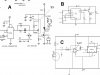
The web is full of high quality IR FM headphones systems. Here is a receiver that uses a fast Pin photodiode with an LC bandpass filter, a digital inverter preamp and a more-modern PLL. Your opamp could replace its FET and your LM565PLL will be OK. This system operates at 100KHz.
 

Attachments

  • ir_receiver.gif
    ir_receiver.gif
    27.1 KB · Views: 860
A couple of things..

Thanks for the advice. Ok a couple of interesting things that you said were regarding the 555 tx circuit firstly how did you calculate the duty for this device. I want to use an IR array I was just wondering how I can supply such high current can I just wire them in series at the output to the 555 or should I use another circuit (driver) from the output - Any suggestions for this.

Ok the regarding the IR headphone circuit what is the purpose of the HEx inverter- ive never used one - How does it amplify the signal. I have the 4046 --I used the 565 because the 4046 has more complicated tuning. How do you think they intend to drive the IR led's they never mentioned?

Thanks
 
Hi Electricman,
The duty-cycle is calculated for a 555 is because it charges the cap through both timing resistors but discharges it through one resistor. Also check its datasheet for its max output current, I think it is 200mA. To get more output current have the 555 drive a transistor.

Can your power supply deliver more current? Forget about using a little 9V battery. You can wire some IR LEDs in series to reduce power wasted in a current-limiting resistor for each one.

A Cmos inverter has a gain of 30 to 50. A Cmos "B-series" gate has a gain up to 10,000.

I couldn't find that project again but who knows if it has been built and works. The application note that I posted from National Semi works OK but is very old.
Why don't you use Google to find a good IR headphones wireless circuit that works well from a good headphones manufacurer like Sennheiser?
 
LED driver

Hi I had a look ion google for hours regarding Ir headphone designs and coudn't find anthing useful. I may buy a cheap pair and disect them I suspect they use a driver IC ive been looking around but I can;t find a suitable one- the only one I found was at:

www.alldatasheet.co.kr/datasheet-pdf/pdf_kor/STMICROELECTRONICS/L601-L603.html

Do you know of any such devices

ive redesigned the ouput stage using a transistor the new design I found from a book. The values I found were supposed to give 60mA fwd current i don't see how though. Anyway if I neglect the control section in the box and set R2 as 20R wont that be switching 9/20 = 450mA through the series array (neglecting the Resistance of the LED's themselves) .

Ive seen a few designs using a FET will that be better?/ be able to handle higher current.

Thanks
 

Attachments

  • mynew.gif
    mynew.gif
    7.3 KB · Views: 806
Hi Electricman,
Don't bother with cheap IR headphones. They won't work very well and will contain cheap Chinese parts you won't be able to find out about or find.

Nice try with designing your own IR transmitter but electricity and electronics don't work like that:
1) A little 9V battery is 9V only when brand new and with no load. If you try to get 450mA out of a new 9V alkaline battery, its voltage would be 7V immediately. With a 60mA average load when new, it will be down to 7.2V and 22mA average in 4 or 5 hrs.
2) You can't neglect the voltage drop (not resistance) of the IR LEDs, they need about 1.5V each, or 6V for 4 in series. Check their datasheet for their max average current rating, it might not be as high as 60mA.
3) The absolute maximum current for your BC548 transistor is only 100mA. Select a stronger transistor or FET for 450mA peak.

Let's investigate an IR transmitter design with your circuit. You want 450mA pulses for good range. You can use a big filter cap across the battery to provide the peak current while the battery provides the average current. You operate the 555 with a 60/450 duty-cycle so the LEDs dont burn out:
1) The four 1.5V LEDs need 6V and the stronger transistor will drop 0.2V, leaving 2.8V for the current-limiting resistor.
2) With a new 9V battery, the current-limiting resistor calculates to be 2.8V/450mA = 6.22 ohms.
3) When the battery voltage drops to 7.2V, the LEDs plus transistor will still drop 6.2V, leaving 1V across the current-limiting resistor and therefore the peak current pulses will be down to 161mA.

You can see how the LED current reduces to nearly 1/3 as the battery voltage runs down. Maybe there is a way to increase the duty-cycle as the battery voltage reduces, but then the battery would last only 3 hrs.
 
new led driver

I found a design for an LED driver it uses a FET - the auothr claims it can switch the LEd at high speed with a peak current of 5A from a 9V source- It doen't have any resistance because the LEd has a high reverse voltage drop at high current. I was thinking of implementing it but do you think its suitable?

Im not too sure how thee Zener and capacitor compination work do you know if this generates the 1us pulse or is it ome kind of regulator. I was thinking of bpassing the zener circuit the LED I plan to use (pictured) can take 10A with 0.2us pulse. Do you know how I can can calculate the pulse width of my output from pin 3 of the 555?

Thanks
 

Attachments

  • drive_187.gif
    drive_187.gif
    48.4 KB · Views: 790
Hi Electricman,
10A of current through an LED! Amazing.
A phototransistor won't detect a pulse as short as 1us, and I doubt that your FM detector will either.

Because this Mosfet circuit uses two different supply voltages , it needs the zener diode to level-shift the 5V output of the 555 to the 9V of the PNP transistor.

The datasheet for the 555 shows its pulse width and duty-cycle calculations.
 
Why bother with a photodiode when I don't think your FM detector will detect it? FM usually works with a 50-50 duty-cycle, 1-27 is extreme.
 
electret mic pre-amp cct

Hi you mentioned earlier that you had a pre-amp circuit for electret mic's - is there are chance you could post it

I have a 2 terminal electret mic and I want to connect it where my audio input should be but im having little joy,do you think its ok for me to connect it directy to my TX opamp.

Thanks
 
Hi Electricman,
This electret mic preamp works very well and can replace your opamp circuit and connect directly to pin 5 of your 555:
 

Attachments

  • electret_mic_preamp.gif
    electret_mic_preamp.gif
    3.3 KB · Views: 854
mic problems

hi thanks for the electret cct i built it on a separate breadboard and input it into pin 5 and it didnt pick up anything. I tried using it for recording via my microphone in of my pc when the gain (100k setting) is up it is extremely sensitive - so i know its wired up ok- I have used a 47uF cap instead of the 22uF.

I changed the 100K for a 1M resistor, it does pick up voice now using the IR system, but you have to speak pretty loudly into the mic to get it working- which isn't gonna be good enough- any idea's how /i can make it more sensitive.

thanks
 
Hi Electricman,
The output level of my preamp circuit is line level and shouldn't be connected to your PC's mic input. It should be about as loud as the line level output of a CD player.
The electret mic should have an output level of about 10mV. With its 100K pot at max resistance my preamp circuit will have a gain of 22.3 and its output will be 223mV which is plenty. With a 1M resistor instead of the pot the gain is 214 and the preamp's output will be 2.14V which should be much too loud.
Maybe the mic isn't working correctly. Are you sure it is a 2-wire electret type and it is connected with the proper polarity? A dynamic mic (coil and magnet) would require the preamp to be re-designed.
 
Mic problems

ok ive got it working with the 100K im using just a 100K resistor, but I still have to talk loudly into the mic- I mean put my mouth on it, to get an output, its a 2 terminal Mic it says its an electret type. ive connected 1 terminal +ve to c1/R1 and the other terminal to ground is this right??[/list]
 
Hi Electricman,
Yes, you have the mic connected to the correct spots on the preamp. Does it have the correct polarity? Its metal case should be the grounded wire.
Did you use 4700 ohms for R4?
Can you record its output on your sound card by connecting its output to the sound card's line input, then compare the level from the line output of a CD player or tuner?
 
With 4300 ohms for R4 instead of 4700 ohms, the gain is increased only 10 percent. You won't notice it.
C2 and the input and output capacitors determine the bass response.
 
photodiode circuit

hi i tried a photodiode in the my reciever circuit, it had an IR pass filter so it helped tremendously to remove the amount of noise from daylight, i want to use a photdiode but my cct in C (in the picture below) was designed for a phototx, do you know how i could make it more suitable for a photodiode? (or maybe i dont have to seeing as it works anyway?)

Ok part 2 - The high current pulse circuit, is not going too well, in the schematic in A do you know what the part in the box is for, it seems to be using a pnp transistor to drive the FET but this tranisistor seems to be connected to the supply, then why have they bothered using the FET at all.
The setup in B was something someone posted on this site its using a PNP transistor to drive an LED it seems simple enough, do you think that setup would be ok, can you recommend any PNP transistors that could handle high current. If I wanted to pulse at 1A from a 9V source im using now like you said earlier it'd be around (7-0.7 less led drop)= about 4V could i negate the current limiter resistor R1

Thanks
 

Attachments

  • txn1.jpg
    txn1.jpg
    65.7 KB · Views: 559
Status
Not open for further replies.

Latest threads

Back
Top