Continue to Site

Welcome to our site!

Electro Tech is an online community (with over 170,000 members) who enjoy talking about and building electronic circuits, projects and gadgets. To participate you need to register. Registration is free. Click here to register now.

  • Welcome to our site! Electro Tech is an online community (with over 170,000 members) who enjoy talking about and building electronic circuits, projects and gadgets. To participate you need to register. Registration is free. Click here to register now.

Filter for voice comms??

Status
Not open for further replies.
opamp gain

hi, thanks again

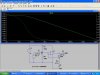
when you say op-amps together have a total gain of 986 from 23kHz to 53kHz. I understand that 986 is from 31.9x30.9 =986 or 29.9db but how did you work out that frequency response from 23-53Khz?

Also what does the 1M resistor do here, is it a filter acting with the 120pf cap

Thanks
 
Re: opamp gain

Electricman2K5 said:
=986 or 29.9db
No, a voltage gain or loss of 1000 is 60dB.

but how did you work out that frequency response from 23-53Khz?
A single RC lowpass filter is 3dB down at its cutoff frequency. It begins dropping at 5 times the cutoff frequency. This circuit has 3 cascaded RC filters so if you want a flat response down to 23kHz, the 3 cutoff frequencies must be around 1.5kHz.

With a gain of 31, the TL071's natural high frequency rolloff causes a cutoff frequency of about 120kHz. Since the circuit has 2 cascaded opamps, they will have a combined cutoff frequency of 60kHz which is a little above 53kHz. I cheated, the combined response at 53kHz won't quite be flat, it will be down a couple of dB.

Also what does the 1M resistor do here, is it a filter acting with the 120pf cap?
The 1M resistor establishes the opamp's input and output DC levels of 0V. Its high value doesn't load down the 100k phototransistor's collector resistor and it doesn't have any current through it (and therefore no voltage drop across it) because the TL071 has FET inputs.
The lowpass cutoff frequency of the 1M resistor and the 120pF cap is about 1.3kHz, near the required 1.5kHz frequency calculated above. :lol:
 
simultion of mic circuit

Hi i simulated the mic input in LT SwitcherCAD3 using the mic as an AC 0.5V source and performed an ac analysis from 1-10Mhz to see the frequency response. This is what i got, Is this what it should look like???
thanks
 

Attachments

  • sim.jpg
    sim.jpg
    100.9 KB · Views: 543
Hi Electricman,
Your sim shows the open-loop gain and frequency response of the opamp without feedback and without the caps. As they usually do, your sim screwed-up! :lol: :lol: :lol: :lol:
 
frequency response

Do you think this frequecny response is ok for the amp cct you suggested for the receiver (using 2 opamps), the opamp parameters are probably not exactly the same as the TL071/2 but it seems ok.
thanks
 

Attachments

  • response.gif
    response.gif
    10.4 KB · Views: 520
Hi Electricman,
The frequency response of -3dB from 1200Hz to 270kHz is fine for your FM modulated IR link and its 38kHz carrier.
Where's the 61dB of gain?
 
+9v and -9V supply from 9v battery?

Hi I want to get -9V to power the PLL currently im using 2 9v batteries with a centre tapping as ground..but i only want to use 1 device for space reasons.

Can I make -9V by passing +9v through it through an inverting opamp terminal????
 
Re: +9v and -9V supply from 9v battery?

Electricman2K5 said:
Hi I want to get -9V to power the PLL currently im using 2 9v batteries with a centre tapping as ground..but i only want to use 1 device for space reasons.

Can I make -9V by passing +9v through it through an inverting opamp terminal????

No!, the opamp requires a -9V supply to produce a -9V output.
 
-9v

I have a PLL that needs -9v I need to use 9V batteries. I can use it with split supply but that means 0nly 4.5V it needs 5V min. Its for a reciever so the gain is important. With opamps At 4.5V ill wont really have much room for battery degradation, a 9v battery will easily read only 8V or so within a week of use!!!
I ordered a (free sample!!) of a MAX1440 switchd cap voltage inverter will invert +9v to -9v supply , around 95% efficient, ive never used one but I hope it can do the job!
thanks
 
Re: -9v

Electricman2K5 said:
I have a PLL that needs -9v I need to use 9V batteries. I can use it with split supply but that means 0nly 4.5V it needs 5V min. Its for a reciever so the gain is important. With opamps At 4.5V ill wont really have much room for battery degradation, a 9v battery will easily read only 8V or so within a week of use!!!
I ordered a (free sample!!) of a MAX1440 switchd cap voltage inverter will invert +9v to -9v supply , around 95% efficient, ive never used one but I hope it can do the job!
thanks

As long as your power requirements are low, it should be fine.
 
Status
Not open for further replies.

Latest threads

New Articles From Microcontroller Tips

Back
Top