Let me try and get this thread back on track. Let's start from the beginning with just the reference materials provided and your actual question.
If you forget everything I have said in this thread so far, and provided me with only the question in first post, part numbers, schematics, traces, my answer would have been:
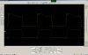
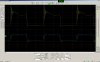
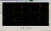
"Yes. Vcc is what is being used to drive the gate voltage so if you change Vcc, then gate drive voltage will also change. That is what you see in the lower traces."
However, this question seems to not have been your original concern. Either, it arose because you mistakenly attributed it to your original concern because everything else or you flubbed up your wording somewhere. If we start, from the beginning, with no text, and only schematics and traces, what is your question? Let's start from the beginning with just the reference materials provided and your actual question.
Alternatively, join me in the chat. I'll be waiting here.

")
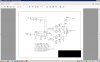
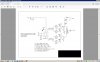
") Well, I am trying to learn and the designer of the exciter for this amp, a gizmo called a U3S by QRP Labs has issued a new firmware that allows one to have 180 degree inverted outputs from CLK0 and CLK1 of the Si5351A chip. This would allow me to simplify the amp and get rid of the 74F74 flip flop, which needs a X2 frequency from the U3S as it halves the frequency as it divides the phase. My issues have been this varying Vcc voltage effect on the gate drive voltage, and getting enough swing from the Si5351A synthesizer chip to drive the IR2110 properly. The MCP1404 seems happy with less swing.
Well, I am trying to learn and the designer of the exciter for this amp, a gizmo called a U3S by QRP Labs has issued a new firmware that allows one to have 180 degree inverted outputs from CLK0 and CLK1 of the Si5351A chip. This would allow me to simplify the amp and get rid of the 74F74 flip flop, which needs a X2 frequency from the U3S as it halves the frequency as it divides the phase. My issues have been this varying Vcc voltage effect on the gate drive voltage, and getting enough swing from the Si5351A synthesizer chip to drive the IR2110 properly. The MCP1404 seems happy with less swing.