Continue to Site

Welcome to our site!

Electro Tech is an online community (with over 170,000 members) who enjoy talking about and building electronic circuits, projects and gadgets. To participate you need to register. Registration is free. Click here to register now.

  • Welcome to our site! Electro Tech is an online community (with over 170,000 members) who enjoy talking about and building electronic circuits, projects and gadgets. To participate you need to register. Registration is free. Click here to register now.

Fault detection meter of 3-phase distribution transformer

Status
Not open for further replies.
hello everyone,
i want to make a fault detection meter for 3- phase distribution transformer, the function of the meter is ( meter will be connected on the output side of transformer)-
1) if there any fault occurs in the transformer which lead to the change in any of the phase voltage then it will show it on the LCD i.e phase failure
2) the meter also continously monitor the 3-phase voltages.
so, my question is which device do i use which can continously monitor the voltage of the transformer. as transformer is on loaded condition so the current on the output side of transformer is high , do this high current affect the meter?
which microcontroller do i use?

thank you
 
Your first job is to divide the voltages down to (5 volts or 3 volts or something that the micro can measure).
From what you wrote, I think you don't care about current. You just want to measure voltage.
You can use any micro that has a ADC. (3 or 4 inputs).
Do you need to measure the voltage to 1%? OR I think the voltage is there or it is not there. So maybe there is a very inaccurate way to test the voltage with out connecting to the high voltage wires.
 
ronsimpson, how do i divide the voltages to 5Volts or 3 V?
and what u said in your last line i cant understand

Scary :)

Just a word of caution here, polyphase power supplies are not like your normal everyday power source from a wall outlet in your home. They carry much higher voltages between phases and are usually capable of carrying much higher currents. They don't play nice if you make any kind of mistake whilst working with them. If you contact the phase conductors accidentally, at the least, you are going to suffer severe burns, at the worst your mates will just be sweeping your ashes into a bag for disposal, so be very careful what you do and how you do it :)


thank you for you advice, by the way do u have any advice regarding the problem which i have stated above:)
 
If you only need to know when a phase is missing, rather than anything about the actual voltage or current, look at using a non-contact method of detection. Perhaps using a small coil as your detector for each phase, followed by a filter and a small gain stage to drive some LED's from a low voltage source, or if you must make contact with the phase conductors, perhaps a phase rotation indicator of some sort might be suitable. Both of these methods can be simply constructed without the use of a Microcontroller and are for the most part very reliable.
 
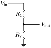
This is a voltage divider. Vin is larger than Vout. In your case Vin might be 440V and Vout is 4.4 volts. The micro reads the 4.4 volts and knows that really means 440 volts.
Resistive_divider.png

Many of the micros can measure 0 to 3.3 volts or 5.0 volts.

I was alluding to a no contact way of measuring voltage. It is not accurate. You can (not connect) but wrap your test wire around the insulation of the power line. You might get a voltage more like 1 volt. You will then tell the micro that, in this case, 1V=440V. If the 1V suddenly becomes 0V then very likely the 440 has become 0V.
 
If the OP just needs to know a phase is missing then three neon bulbs (With limiting resistors) connected in delta configuration would be the simple solution. The OP needs to define his requirements more precisely. Is it just the loss of a phase that needs to be detected ? If it is voltage out of tolerance what accuracy is required ? Does the OP have access to the star point. We are probably all assuming the three phase is the normal distribution voltage. (240 volt neutral to phase or 415 volts phase to phase / 120 volt neutral to phase or 208 volts phase to phase) and 50 or 60 HZ. Is this the case or is it some other voltage and frequency. (Or even some high voltage used for power distribution eg 132 KV) Also how does the output need to be displayed ?

Les
 
Last edited:
Hi.

First of all - failure in a distribution transformer is lethal. The local power company had such a failure in a transformer in a nearby transformation station (big concrete bulding). That explosion was so powerful that the whole first floor was literally lifted up.

If the goal is to prevent shortcut in case of three phase transformer failure , measuring just the voltages is far from enough, and probably would not help a bit. You need to measure current at primary side and current at secondary side, and then compare. If the transformer is about to have a failure (internal current flow between broken windings) there will be a difference between input current and output current (I assume you use current transformers with a ratio adapted to the specific transformer, and have taken into account the transformer power loss), and the meassuring device will be wired to a circuit breaker to prevent a fatal incident.

There is another thing you must take in account, that is how the transformer is connected. A very common scheme is Dyn11, wich means that there will be a phase shift between secondary and primary side, and if one phase at primary side is disconnected, yoy'll still have around half the rated voltage at secondary side.
 
If you only need to know when a phase is missing, rather than anything about the actual voltage or current, look at using a non-contact method of detection. Perhaps using a small coil as your detector for each phase, followed by a filter and a small gain stage to drive some LED's from a low voltage source, or if you must make contact with the phase conductors, perhaps a phase rotation indicator of some sort might be suitable. Both of these methods can be simply constructed without the use of a Microcontroller and are for the most part very reliable.

As i am thinking of using current transformer of the specific ratio of the transformer with a fixed output of CT 1A as the output of CT's are low then it will be easier to measure futhur i wil connect the outputs CT to the circuit
 
hello friends,
As i am thinking of using current transformer of the specific ratio of the transformer with a fixed output of CT 1A as the output voltage and current of CT's is low then it will be easier to measure. futhur i will connect the outputs of CT to the circuit
so, now my question is that-
Q1) is there any IC available which can measure voltage and also can be interfaced with any microcontroller ????
Q2) for measuring the 3phase voltage do i have to use 3 indivisual voltage measuring IC or is there any IC available which can measure Polyphase voltages?
 
Last edited:
Hi.

First of all - failure in a distribution transformer is lethal. The local power company had such a failure in a transformer in a nearby transformation station (big concrete bulding). That explosion was so powerful that the whole first floor was literally lifted up.

If the goal is to prevent shortcut in case of three phase transformer failure , measuring just the voltages is far from enough, and probably would not help a bit. You need to measure current at primary side and current at secondary side, and then compare. If the transformer is about to have a failure (internal current flow between broken windings) there will be a difference between input current and output current (I assume you use current transformers with a ratio adapted to the specific transformer, and have taken into account the transformer power loss), and the meassuring device will be wired to a circuit breaker to prevent a fatal incident.

There is another thing you must take in account, that is how the transformer is connected. A very common scheme is Dyn11, wich means that there will be a phase shift between secondary and primary side, and if one phase at primary side is disconnected, yoy'll still have around half the rated voltage at secondary side.

hello,
yea you are correct but my goal is not to prevent fault but after the fault the device which i am thinking to make can tell which fault is this for example- phase failure
as switch gear devices are available in the market which can pre detect the faults which are going to occur on transformer for eg- earth fault protection device
thank you
 
If the OP just needs to know a phase is missing then three neon bulbs (With limiting resistors) connected in delta configuration would be the simple solution. The OP needs to define his requirements more precisely. Is it just the loss of a phase that needs to be detected ? If it is voltage out of tolerance what accuracy is required ? Does the OP have access to the star point. We are probably all assuming the three phase is the normal distribution voltage. (240 volt neutral to phase or 415 volts phase to phase / 120 volt neutral to phase or 208 volts phase to phase) and 50 or 60 HZ. Is this the case or is it some other voltage and frequency. (Or even some high voltage used for power distribution eg 132 KV) Also how does the output need to be displayed ?

Les

Hello,
but when the phase failure occurs at the LV side huge voltage difference occurs on phases due to which the neon bulbs will blow off( as u said of using neon bulb)
my aim is to show which kind of fault occured in the transformer (either phase failure or earth fault) by the help of automatic meter
and the three phase voltage which you are assuming is normal distribution voltage. (240 volt neutral to phase or 415 volts phase to phase 50Hz)

Thank you
 
Q1) is there any IC available which can measure voltage and also can be interfaced with any microcontroller ????
Q2) for measuring the 3phase voltage do i have to use 3 indivisual voltage measuring IC or is there any IC available which can measure Polyphase voltages?
There are many ADCs that have 1, or 2 or 4 or 8 or 16 inputs.
There are many micros that can measure analog voltages directly. (maybe not quite as good as with a separate ADC)
Attached is the data sheet for a 4 input ADC. 16 bit which is probably too good for this job.
 

Attachments

  • MCP3428.pdf
    944.9 KB · Views: 254
If the correct value of resistor in series with the neons was was chosen then the neon bulbs would not blow. Now that you are giving a little more information I agree that the neon bulb solution is too simplistic. I have never worked on power distribution networks so some of my assumptions may be wrong. I assume the transformer you are referring to is in a substation. I also assume that the secondary is star wound with the star point going out as the neutral conductor and that it is also grounded at the substation. As we have access to the star point we can use resistive potential dividers to bring the voltage down to suitable levels to work with. (If we did not have access to the star point then I think we would have to use three small transformers (Each connected between a pair of phases.) to drop the voltage and isolate it.) If we chose to divide the 240 volts by 24 we could do the measurements on about 10 volts with respect to earth. We could take six sets of readings. Three would be star point to each phase and three between phases. We could use op amps to convert the phase to phase voltages to a voltage with respect to ground. These six AC readings would have to be converted to DC to measure them with the A to D converter in a micro controller. You would need to decide weather the rectification just gave the average value or weather you needed the true RMS values. When you talk about an earth fault are you referring to a short between some random point on a winding and the transformer core (Which is presumably earthed.) or some other type of earth fault ?

Les.
 
Just wrap a wire around the line out wouldn't need much maybe ten turns test its output with dvm and then make changes less wraps or more use a bridge to output dc that can be read with the adc of a uC.
 
I would suggest three small transformers, each one between a phase and the star point, to transform the supply voltage down to safe levels. There may still have to be resistors to divide the voltage, but at least the voltages will be safe without dividers.
 
I was thinking about measuring line voltage and line current. With that much information you could rough-fully know the impedance of the transformer (or one leg of the transformer). If the line voltage drops 1% more than it used to (under load) this is a sign of bad things to come.
 
I was thinking about measuring line voltage and line current. With that much information you could rough-fully know the impedance of the transformer (or one leg of the transformer). If the line voltage drops 1% more than it used to (under load) this is a sign of bad things to come.

and how can i do that (measuring line voltage ND CURRENT)
 
You would measure the voltage by rectifying the low voltage from the potential dividers or small transformers. You would measure the current by rectifying the output of the current transformers on the output of the power transformer. You would probably need to use active rectifiers using op amps rather than just using diodes. (You may also want to add circuitry to give true RMS output. You will find circuits to do this if you Google "true rms rectifier") Once you have the AC voltage and current represented by DC voltages you would measure them using either the internal ADC which is available on most micro controller families or an external ADC. You could drive a display (LED or LCD) directly from the micro controller or send the data via a serial link or Blutooth to a PC for further processing and display. Chose one of the micro controllers that you are most familiar with programming.
Overnight I thought of another approach to your problem. If you had a phase locked three phase sine wave inverter you could compare the instantaneous voltages on each phase between the power transformer output and the output of the inverter

Les.
 
Status
Not open for further replies.

Latest threads

New Articles From Microcontroller Tips

Back
Top