Continue to Site

Welcome to our site!

Electro Tech is an online community (with over 170,000 members) who enjoy talking about and building electronic circuits, projects and gadgets. To participate you need to register. Registration is free. Click here to register now.

  • Welcome to our site! Electro Tech is an online community (with over 170,000 members) who enjoy talking about and building electronic circuits, projects and gadgets. To participate you need to register. Registration is free. Click here to register now.

Fast overload switch

Status
Not open for further replies.

throbscottle

Well-Known Member
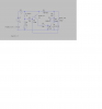
I need a cutout for my motor controller, came up with the attached. Works in LTSPice. The relay contacts would be connected so they disconnect the power and latch-up the relay instead (would require manual reset). The "boost cap" is to ensure the relay closes in between disconnecting and re-connecting power to itself. I1/R4 represents the load, R5 is to absorb the voltage differential in the simulation, V1 would be the actual psu. R_sense isn't a real value, its just for the simulation. I decided to use a 5v relay with a series resistor, to give the boost cap a longer discharge time - I know it does nothing in the simulation, it's just what I came up with. R6 is the "go faster" resistor. I just tried different values to find that one.
R2 is there because I want to be able to inject another signal to Q2's base.

I was going for low component count with this hence it's rather primitive.
 

Attachments

  • fast-cutout.png
    fast-cutout.png
    47.8 KB · Views: 200
  • fast-cutout.asc
    2.2 KB · Views: 144
Rather than primitive, make it excellent and reliable.

It may work but is quite lossy for a motor driver. (1+0.9)/(1.9+8)
Also the 5V relay driver is quite lossy.
A 10A 5V relay typically takes 50 ~80mA ( 0,5~0.8%) with wide variation. which represents ~ 60~100 Ω approx
Thus if R3 is the coil resistive your equivalent circuit should have the reverse diode across R+L.

However D1 may drop 0.9V or 18% at 50mA is marginal and just means it turns on much slower than say 10ms spec.
Turn off is 0.5V worst case typ. depends on source.

Normally current sense factors voltage drop power dissipation and load regulation or impedance ratio.
A 60~75 mV shunt is typically used with an Shunt monitor or Op Amp or comparitor to give the required sensitivity with a LPF to prevent surge currents which are up to 8x rated current from tripping the circuit.
Op Amp or comparator and a flip flop costs more than a 0.9Ω 3W resistor.
A PTC could also be considered.

Try harder.
 
I think I made too much ambiguity in my diagram, R5 and R4 don't really exist, and R3 isn't part of the relay coil, it's a real resistor though since RL1 isn't a real relay, R3 doesn't have a proper value either. The sense resistor I chose the value for proof of concept, rather than based on real life, I'd actually be using 0R33 there. Also it's a small motor from a printer, when it drew enough to blow my H-bridge I was really surprised. Anyho, good point about the LPF, I hadn't thought of that - is a large cap across the sense resistor enough in this case? I agree an IC would be simpler to use - I ended up with this because I was trying to use a single transistor and found the gain wasn't high enough.
Interesting point about D1, I didn't think it would cause a slowdown. The idea is so the cap can be charged, but can only discharge through the relay and it's dropper resistor (which gives it a little bit longer to pull in)
But, since you mentioned a PTC, I think that is the obvious answer, really - I should just pop in a 2A polyfuse and be done with it!
 
Yes a properly sized PTC may be all you need unless you want to clock a counter for Fault event counter or latch.

Some variations in 2A SMT or THT trigger and recovery times vs Current for a 2A holding current. The question is how long does it take PTC to reach 85'C and switch resistance exponentially. This is the typ. regulating temp. and what is the motor temp under this condition such as locked rotor.

upload_2015-3-17_14-15-29.png
 
Hmm, for me it's the H-bridge that I have to protect, 2 seconds is probably far too long - and I see 2 secs is fast compared to some others. It's a **broken link removed**, very simple. OK back to plan A then... PSU probably isn't strong enough to kill the motor.
It's only the feed motor for a pcb drill so I don't need counters or anything fancy like that. I was originally going to simply have a current limiting resistor but decided it was too wasteful of power and really I need to reset the circuit if it gets locked up, however I still might be able to go with it. Will try to have an experiment at the weekend (or maybe the weekend after :( )
 
Ok I ditched the latching relay idea. So now it is just a current sensing Schmidt trigger with a lot of hysteresis. It could probably be better, I just guessed the values initially and tweaked them in LTSpice. So it can pull the inputs to the H-bridge low and turn off the motor.

The problem I have now is that I still need it to latch up so the motor can be re-positioned manually.
 

Attachments

  • snapshot1.png
    snapshot1.png
    55.9 KB · Views: 150
Status
Not open for further replies.

Latest threads

New Articles From Microcontroller Tips

Back
Top