Continue to Site

Welcome to our site!

Electro Tech is an online community (with over 170,000 members) who enjoy talking about and building electronic circuits, projects and gadgets. To participate you need to register. Registration is free. Click here to register now.

  • Welcome to our site! Electro Tech is an online community (with over 170,000 members) who enjoy talking about and building electronic circuits, projects and gadgets. To participate you need to register. Registration is free. Click here to register now.

ESR Meter Modifications

Status
Not open for further replies.

bryan

Member
Hello:

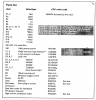
Looking to build a simple ESR meter. Attached is the schematic and parts list, but I can not find a 100ua panel meter locally, but do have a 50ua available. What modifications to the circuit would be needed to accomodate the 50ua vs 100ua.

Full project article is at this site.

http://mark-lawton.com/capacitor-esr-meter-project/

Thanks in advance
 

Attachments

  • Capture1.PNG
    Capture1.PNG
    37.1 KB · Views: 1,705
  • Capture2.PNG
    Capture2.PNG
    42.3 KB · Views: 1,428
  • Capture3.PNG
    Capture3.PNG
    96.5 KB · Views: 542
Hi,

You can probably get away with just doubling the value of R13, as long as you can adjust for full scale with the pot.
 
To be honest with you, that is a bit of a dodgy design. It will do what you want I suppose, and is cheap enough to build, but you will likely blow it up the first time you connect it to a highly charged cap in a power supply. Momentary lapse of concentration and you let the magic smoke out. It happens to us all :)

A much better piece of kit to build can be found here: **broken link removed**
If you're russian isn't up to it, try google translate ;)

Thanks, from the article the author has used the design for a number of years and apparently has proven reliable. Just have to be careful I guess. The AVR- digital project looks neat, but don't want to get tangle up in anything too complicated
 
Last edited:
Thanks, from the article the author has used the design for a number of years and apparently has proven reliable. Just have to be careful I guess.

Yes it's fine - just don't be crazy with it :D

As for the meter, simply stick a shunt in parallel with the meter, equal to it's internal resistance (it's how you make a 100uA meter out of a 50uA one).
 
Thanks Nigel. So for the shunt, just measure the resistance of the meter and then add a equivalant resistor of the measured value in parallel to the meter?
 
Thanks Nigel. So for the shunt, just measure the resistance of the meter and then add a equivalant resistor of the measured value in parallel to the meter?

Yes, apart from the meter should have it's resistance stamped on it somewhere anyway.

If you're measuring the resistance, be careful of how much current you feed through it.

Here's everything you need to kow about shunts and multipliers:

**broken link removed**
 
Hi Bryan,
I put off building an ESR meter again and again, and finally took the shortcut and bought a kit at Main Electronics. It only took a couple hours to assemble and seems to work well.
**broken link removed**
it did take a chunk of coin off me, but I do make good use of it.
 
Last edited:
Hi Bryan,
I put off building an ESR meter again and again, and finally took the shortcut and bought a kit at Main Electronics. It only took a couple hours to assemble and seems to work well.
**broken link removed**
it did take a chunk of coin off me, but I do make good use of it.

I used a home made one for years, then I bought this one:

http://www.peakelec.co.uk/acatalog/jz_esr60.html

They are absolutely great! - PIC based apparently - and not much more than your kit.
 
I used a home made one for years, then I bought this one:

https://www.peakelec.co.uk/acatalog/jz_esr60.html

They are absolutely great! - PIC based apparently - and not much more than your kit.

Yes, it looks better; I prefer the LCD over the seven segments. There is something about walking in a store (Main Electronics is local) and being able to handle the thing before you buy, and take it home with no wait. Well, at least only a short one while assembling. :p

EDIT: the one I got you must discharge the caps first; in the one Nigel got you don't have to!
 
Last edited:
Just a quick follow up - I've changed the battery in my ESR meter today.

It uses the following chips:

PIC16F873a
MAX4614 CMOS switch (x2)
26241 opamp (x2)
4903 double 5V regulator (x2)
2931 5V rgulator
 
Hi Bryan,
I put off building an ESR meter again and again, and finally took the shortcut and bought a kit at Main Electronics. It only took a couple hours to assemble and seems to work well.
**broken link removed**
it did take a chunk of coin off me, but I do make good use of it.

Hi BeeBop

DIY one I made was flakey, bought one off of Ebay MESR-100. Complete piece of rubbish. They do have a newer model, maybe better.

Untitled.png

All the time and money and I should have just purchased the Blue Esr. What's your impression of it, accurate, easy to use?. Would you recommend, and trust it.
 
Status
Not open for further replies.

Latest threads

New Articles From Microcontroller Tips

Back
Top