Continue to Site

Welcome to our site!

Electro Tech is an online community (with over 170,000 members) who enjoy talking about and building electronic circuits, projects and gadgets. To participate you need to register. Registration is free. Click here to register now.

  • Welcome to our site! Electro Tech is an online community (with over 170,000 members) who enjoy talking about and building electronic circuits, projects and gadgets. To participate you need to register. Registration is free. Click here to register now.

ESP8266 control system

Status
Not open for further replies.
Hello,

I have a few questions about ESP8266 D1 mini. I plan to use it in a simple system. I will hook this things to it:

1) 2x red led, 2x green led. Only 2 leds will be turned on at the same time, if all is working well, 2 green ones will glow, if there are any errors in the system, 1 or 2 red ones will glow. I will use such resistor that each led will draw at most 10mA, possibly even 5mA, since the system will be in a dark place and leds will be clearly visible even at low power. I plan to power them from the esp8266 but if there is a better way, i would like to hear it.
2) relay board with 2 relays on it. Relay itself will be powered from external source and esp8266 will only send signal to either 1 or both relays at the same time
3) 4x DHT22 sensor that will be powered by the esp8266 itself

I have a few questions.

1) is this setup within safety margins regarding how much juice the ESP8266 can suply ? If not, is there a better way of doing this ?
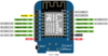
2) usualy when doing things with esp8266 board pins, i just start at D0 and then keep adding things to pins i need. So in this case i would look leds to pins D0 - D3, relay board to D4 - D5 and DHT22 sensors to pins D6 - D9. Is this an ok way or should i use certain pins for certain thing ? I am not using pwm or USART or anything like that at the moment so i am asking purely from the perspective of power handling of different pins and what is optimal.
3) all 10 devices will be connected to the same ground pin on esp8266 board (when i say esp8266 pin i mean esp8266 board pin), will that be a problem ?
 
Last edited:
Each pin on the esp can provide 12 mA (corrected - the ESP32 can handle 40mA/pin). but I like to keep it less (5 to 10mA). Many modern LED (high brightness LEDs) Are plenty bright at 5 mA).

as far as ground pin, the current flowing out of a pin, through a resistor, through LED to ground is done there, nothing flows back into the ESP after that. It flows back to your power source so you are not actually connecting everything to the esp ground pin, per se.

make sure the relay board is 3.3v comparable because the esp pins are only 3.1v or so. Make sure it activates the relays and make sure the relay board does not require more than 20 or 30mA.

you should be ok connecting the sensor directly to the esp.

there are no published "banks" of pins that distribute power or max load for a given set of pin groupings so you are free to load the esp as needed but look up the max load, I think it is 150 mA on the external pins - 0.33 watt. Make sure your power supply can give at least 500 mA, plus the current load from the sensors and LEDs.
 
Last edited:
Thank you for your response.

Outside power suply is not an issue, i havent yet decided which power suply i will use but it will be anywhere from 10 to 90W capable. I will then use step-downs to get 3V for relay and 5V for ESP8266. The only issue is if ESP8266 will be able to handle the load i put on him.

The relay board i am using is in the link below, it uses 2x JQC3F relay (full name written on it is JQC3F-03VDC). Sadly i couldnt find any information on how much mA the diodes draw, but considering that a very bright led light can work on only 5-10mA, i really think i am safe there. I will try to measure it with multimeter but the current might be so small i wont be even able to detect it.

2 channel relay - link to aliexpress

As for those 4 LED lights and 4 sensors i mentioned, they will be powered by ESP8266 board. So total wires going into ESP8266 ground pin will be 10 - 4 from LED lights, 4 from sensors and 2 from the relay control pin. I have to admit i am not in the clear here ... i always thought the current that comes through the + wire into a device and then goes out of the device through - wire into the ground pin is the same. Am i wrong here ?

Like i said i will only use 2 LED lights at once and i will use such resistor to limit current draw to 5 or 10mA, which as you said will be plenty bright enough. So that is 10mA per pin and 20mA together for the board. As for the 4x DHT22, the datasheet says 0.3mA per sensor while measuring, so that is 1.2mA together and not even worth mentioning, besides, DHT22 are 5V tolerant so i power them by 5V pin on ESP8266 board. So if we assume that relay uses almost nothing to trigger the 2 diodes, sensors use 1.2mA and 2 leds use 10-20mA, that is combined at most 21.2mA + diodes, which is in the safe area, right ?

It would be great if there was a simple explanation for ESP8266 board. I have been using those boards for years and they are fantastic for their price of 1.5$ on aliexpress. But it would be great to have a simple datasheet i could trust for the whole board, to see how things are connected and to be sure how much i can draw from any single pin. Because i have been reading a lot about ESP8266 and i have found various data for single pin power draw, anywhere from 10mA to 100mA. Also for the 5V pin, some said its about 1A and others said that 5V pin is directly connected to 5V microusb input, which would mean it can suply as much current as the power suply powering the board is able to suply, which in my case would be like 20A (which i am sure would melt the board .. ). Also the board total mA capability would be great to know .. i only use 2 LEDs now but in future i might need to operate 10 LEDs

edit: i see that i am adding to the confusion when i say ESP8266 ... when i say ESP8266, i really mean the ESP8266 d1 wemos board and not the ESP8266 chip itself. And when i say pin, i mean the physical pin to which i attach the sensors and leds, not the pin on the chip itself. I hope this will clear some things up :)
 
Ok, this is good to know, i will keep that 12mA in mind and try to keep it to about 5-8mA per pin, talking about ESP8266 board pin. How about total power of the entire ESP8266 (board) ? And also 3.3V and 5V pins, again, on the ESP8266 board ?
 
There are no 5 volt i/o pins. Its not going to operate dependable if you used them at 5 volts
 
This is how my board looks like and on the right side there is a 5V pin. Just to clarify again, when i am talking about pins i mean pins on ESP8266 wemos d1 board. I do not care about pins on ESP8266 chip since i cant connect directly to the chip, i can only use the pins on the board itself. And while some pins on the board are directly connected to pins on the chip, that is not true for all the pins. So again, when talking about pins, i am talking about ESP8266 wemos d1 board pins.

Ok, so about that 3.3V and 5V pins on the board. It would be good to know how much juice they can suply. I read somewhere that 5V is connected directly to the input with which i power the board itself, which would mean i could draw quite a lot of amps from it. And 3.3V pin it would be great to know also because then maybe i can power the leds from this 3.3V pin and just connect the grounds to the actualy gpio pins and reduce the stress on them.
 

Attachments

  • WeMosD1Mini_pinout.png
    WeMosD1Mini_pinout.png
    120 KB · Views: 254
The board is not made for supplying Amp's Maybe 500 mA at best from the 5 Volt pin
The regulator is rated for 500 mA But that would probably be pushing it.
 
I would really like to come to the bottom of this. Because i remember reading that 5V pin is being powered from external power suply that you give to the ESP8266 board. While i never plan to come close to 500mA, it would still be great to know that 5V pin on wemos d1 can go higher. As for 3.3V pin, i remember that its limited by regulator and that its quite low. Would be great to find some data, i have problem finding it though
 
The 5v pin is connected to the 5v USB input. So it's limited to what the USB source can supply if the USB connector is used for power input. Otherwise, it's the 5 volt input to the board from whatever the 5 volt supply is. The 3.3v regulator is an SOT-23 linear regulator, so I wouldn't sink too much from it, as it's also powering the ESP8266.

The official word from Espressif is that ESP8266 pins ARE 5-volt compatible, so you could connect the LEDs to the 5v source and remove that load from the one-board regulator.

Note that ESP32 pins are expressly not 5-volt tolerant.
 
At one time Espressif, had in their documentation that the ESP8266 GPIO was 5 volt compatible. Now Espressif has removed the reference that the ESP8266 is GPIO 5V tolerant. Thus it is, to me, a matter of luck if and for how long a 3.3V device is going to work with 5 volts on its GPIO pins

And as for the D1 there is no way that board can power anything thats a Amp thru the USB and out the 5 volt pin the power rails are to small
 
Thank you for your answer. Its great about the 5V pin, so i could use it to power leds, obviously i would use resistors to drop that voltage to under 3V as those leds would die on 5V.

I am a bit confused about the Expressif part. I read it over and over that ESP8266 pins are NOT 5V tolerant. I am not sure i want to risk it.

I have a very important question here, please do not skip it.

Ok so lets say i am powering 10 leds. I connect the + wire to 5V pin on wemos d1 and then use a resistor to lower that voltage to 2V, meaning there will be 3V on resistor, 2V on led light, and the - wire from led light will go to GPIO pin on wemos d1.

1) lets assume GPIO pins are 5V tolerant, which they probably aren't as you said, but lets assume for the second that they are. Lets say those 10 leds together use 100mA, which is far more than a single GPIO can suply. But in this case, GPIO isnt suplying anything, instead its the 5V pin that is suplying and GPIO pin works as ground. So how much amps is actualy going into the GPIO pin ? Is it 100mA or is it zero since its been used ? Would GPIO pin survive this, again, under the assumption that the GPIO pin IS 5V tolerant (which it probably isnt, but anyway)

2) ok so now we say that GPIO pins AREN'T 5V tolerant. So instead of resistor, we use a step-down to change voltage from 5V to 2.5V. Other than that, we connect the same way, 5V pin goes through step-down into led and the - wire goes to GPIO on wemos d1. What is the voltage on that GPIO pin, is it 5V or 2.5V ? Will the pin survive ?

I am sorry for basic questions, i am learning as i go and have problems with some things, as are those 2 questions here and would help me greatly if you could answer them
 
Regarding 5 volt compatibility, this Hack-A-Day article refers to Facebook posts by Teo Swee Ann of Espressif Systems stating the ESP8266 is 5-volt tolerant used in open drain applications such as switching an LED to ground.

He goes on to explain that they deleted this statement as too many people were confusing 5-volt tolerant I/O pins as meaning the ESP8266 could be powered by 5 volts, which it cannot.
SmartSelect_20200728-173147_Firefox.jpg


SmartSelect_20200728-173217_Firefox.jpg
 
The current through the LEDs goes through the chip to ground (where else could it go?). So if 10 LEDs each drawing 10mA are illuminated simultaneously, each I/O pin sinks 10mA, and the ESP8266 ground pin sees 100mA + whatever the ESP9266 draws itself.

I don't see any spec for maximum ground pin current draw, so sinking 10mA each from 10 LEDs should be ok.

Regarding your "step down" – the alternative to sinking the LED current directly is to use a NPN transistor or N-channel MOSFET to switch each LED. If you did this, the LEDs could be connected to even 12 volts or more (depending on the rating of the transistor or MOSFET) and the 3.3 volt signal will switch the transistor/FET using almost no current.
 
Last edited:
Thank you for all the inputs !!

Ok so the safest thing regarding leds would be this i am assuming:

1) i connect the plus wire to 3.3V pin on the wemos d1. That pin should have no problem suplying 100mA since its rated around 500mA (and part of it goes to power the board and i shouldn't push it to hard, but 100mA sounds like a safe thing). So then i hook up the + wire into a resistor and then from the resistor to + pin on led light. And then the - wire from the led light goes into wemos d1 GPIO. And when the GPIO pin will be high, light will be off, when GPIO pin will be 0V, the current will flow and led light will be on.

The only thing that bothers me is the need to use a separate resistor for each led, bothers me because all the resistors would be of the same value. I was toying with the idea to use the same resistor for all the leds but i think that would cause problems cause current would have multiple choices where to flow.

I read about transistors and MOSFETs but i never actualy got to use them or to learn how they work. If you have some good link to some tutorial on the transistors or MOSFETs i could use, it would be great since i am just learning as i go.
 
I have a few questions ...

1) I plan to power 3 LEDs from 3.3V pin on the ESP8266 board. Why ? Because that 3.3V pin can handle a lot more current than the IO pins can. And the negative wire will go into 3 separate IO pins. That way when i make pin high, there will be no current flowing and LED will be turned off. And when i pull the pin low, current will flow. And since the IO pin is connected to ground in this manner, it should be a lot less stress for the ESP8266 board as opposed to me using the IO pin to power the led and connect the negative to ground. Am i right in this ?

2) I will need 3 resistors to power LEDs. But since all resistors will be of equal value since LEDs are identical ... what if i would just use a single resistor ? So i would connect 3.3V pin to a single resistor and out of that resistor would go 3 wires, each to its own + of the LED. And then the minus from each LED would go to its own IO pin. That should work, right ?

I added a scheme of 3 situations. The top one obviously doesn't work properly since leds will be powered even if only 1 IO pin works. The bottom one should work because if you cut the + from any LED, it simply will not get power no matter what. In this situation we use IO pins to suply the voltage. And last, the right one, this is the one i plan to use. IO pins act as ground in this case and the power comes from 3.3V pin. They all share the same + pin, but since their ground is separate it should work as intended. Please correct me if i am wrong.


20200810_200651(0).jpg
 
According to a thread on the Expressif forum, ESP8266 I/O pin capacity is:

Source: 12mA (supplying V+)

Sink: 20mA (acting as ground)

12mA is more than enough current to drive an LED, so either method will work.

You can use a common resistor for all three LEDs, provided that only one will ever be illuminated at a time. Seems like a lot of flexibility to give up to save the cost of a couple resistors.
 
This changes things quite a bit and it does seem that in the past i was wrong. Because i often ran things in parallel, granted, i used a step-down or step-up, but i always assumed, the step down will simply draw more power if i connect another device in parallel, i never thought about components being power starved.

Would it change anything if instead of 1 resistor i used a step-down, going from 12V to about 2V ? And then out of the step-down, 3 LEDs in parallel ? Sadly, they must be capable of turning on either 1, 2 or 3 at once. The problem is i am not sure i have the right resistors at home and ordering them now will mean i will have to wait them for 2 months .. and i have to finish this thing in about 3 weeks.

There is a third option ... i could go check my recycling bin. I have about 10 old broken computer power suplies there and some old motherboards and GPUs. Maybe i can salvage the right resistors from them.
 
What do you mean by a 'step down'?, if you mean a switch-mode converter it's somewhat more complicated than a single resistor? - which you would still need anyway.

But you generally shouldn't put LED's in parallel, except under certain circumstances, and using identical LED's.
 
Status
Not open for further replies.

Latest threads

New Articles From Microcontroller Tips

Back
Top