Continue to Site

Welcome to our site!

Electro Tech is an online community (with over 170,000 members) who enjoy talking about and building electronic circuits, projects and gadgets. To participate you need to register. Registration is free. Click here to register now.

  • Welcome to our site! Electro Tech is an online community (with over 170,000 members) who enjoy talking about and building electronic circuits, projects and gadgets. To participate you need to register. Registration is free. Click here to register now.

Energy Havesting - Generator questions

Status
Not open for further replies.

edtrink

New Member
Hello All,

I'm working on an energy harvesting project that uses a stepper motor as a generator to convert rotational kinetic energy to electricity for charging a battery. The battery will be used to power a wireless sensor. The motion of the motor will be intermittent, so I need to extract the most amount of energy each cycle. The drag on the pulley is neglegable due to the size and mass of the system.

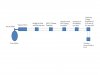
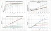
I’ve created graphs of the voltage and current output of the motor at various rpm and loading resistances. I've also included a block diagram of the components I'm planning to use.

The stepper motor can output voltages above what the solar charger can handle (30 volts max) at the RPM it will be operating at, so I use a voltage regulator to limit the input voltage to the charge controller. The solar charge controller is used to prevent the battery from being overcharged. The SLA battery is then used to feed the sensor/battery through a switching voltage regulator.

I would like to know if I will need to put a series resistance in line with generator to provide the maximum output to the battery. I don't think that the battery will be discharged very much per day so the charging current will be small. I tried to connect this system to the SLA battery without the charge controller to see if it would charge the battery and it wouldn't output enough voltage without a resistance inline.

I realize that this system is not extremely efficient and these components could be combined into a single board, but I wanted to use robust off the shelf components for this project.

Thanks,

Ed
 

Attachments

  • Generator Block Diagram.jpg
    Generator Block Diagram.jpg
    29.4 KB · Views: 166
  • Stepper Output.JPG
    Stepper Output.JPG
    150 KB · Views: 155
A large unloaded stepper can put out 300 volts; smaller ones a lot less. However, this is the UNLOADED voltage. Load it down and it drops drastically.

Ever take two large stepper motors and wire them together? Works a lot like those old pre-1980 syncro systems, but without external power. You can't expect a step-in for a step-out, however.

I've used steppers as "digital" rotary encoders. Since the output of the two windings is in quadrature, they can be used to indicate rotation direction as well as "distance" from the number of pulses. Again, the idea isn't bad, but at low rotation speeds, you suffer in output and signal reliability.

Dean
 
Input

The pulley connected to the hook block on a crane. The raising and lowering of the hook causes the pulley to rotate. The motor speeds that I'm expecting are around 170 mean and 280 rpm max for each cycle.

I used a stepper motor so that I can achieve the voltages I need to charge batteries with out using gearing.

Regards,

Ed
 
What's the point?

This isn't some sort of free energy scheme is it?

The only reason why this might be useful is so you can reclaim some energy lost in breaking a load being slowly lowered.
 
The point of this is to power the wireless sensor without cables to another power source. Ideally I would like to power the sensor on a daily basis with the energy harvested from the pulley or a solar panel so the on board batteries do not need to be changed or externally charged. I already have the solar panel system figured out. These two systems would be used redundantly to make sure the sensor does not run out of power ever.

I will restate what I'm confused about:

I want to use the generator to charge up a sealed lead acid battery that will feed the sensor. I need to extract the maximum energy from each cycle for this to work. I've calculated the internal resistance and plotted it on the attached charts. From maximum power theory, I should have a load of around 40 ohms to extract the maximum power at the average operating speed of 170 RPM. I found that without an in line series resistance, the voltage drop was too much (think short circuit) to charge the battery. The problem that I'm running into is that as the battery charges, the battery resistance changes and so does the generator output. Is there a way to maintain a 40 ohm load on the motor, to provide maximum power, without the motor "knowing" about the change in resistance of the battery as it’s charged?


Ed
 
I don't think your generator cares a whit if it sees a resistor; it just transfers maximum power at an optimum voltage and current.

It seems to me that the ideal "black box" to put between the generator and the battery is a uprocessor controlled switch-mode power supply configured in "buck" mode. Typical efficiencies can run 75% to 95%.

The control algorithm for the switcher has two possible states: Either the generator is capable of producing the maximum allowed charging current to the battery (look up the spec for your battery, but its like 0.2C), in which case the control algorithm does whatever it has to to regulate the charging current at a safe level. After the battery reaches a "full charge" voltage limit, then the controller switches to a constant-voltage to the battery mode.

If the generator is not capable of generating the maximum allowed charging current, then the algorithm controls the PWM rate/duty cycle so as to maximize the battery charging current. For sure, when the charging current is maximized, the "E/I loading" presented by the switcher input to the generator is "optimum" for power transfer.
 
...

I found that without an in line series resistance, the voltage drop was too much (think short circuit) to charge the battery.
...

I don't mean to sound like a jerk but you should re-do that measuremernt. :eek: Theres no way that stepper "generator" was putting more current into the battery through a series resistance than it was via direct connection to the battery.

What kind of diode bridge setup are you using? And is the motor bipolar or unipolar, and voltage/current etc?

Mike makes a good point that you can use a buck converter to run the motor near its max power point but I'm not sure you need to do that. You say the motor will run at 170-280 rpm, do you know what % of the day the motor will be running and what is the total daily energy requirement of your load?
 
Mr RB,

I found that the voltage drop was to much for the generator to charge the battery. Please look at the attached charts, specifically the voltage vs rpm and load. At very low resistances, like 1.6 ohms, the voltage is too low to be usable.

The motor is a two phase motor setup with two full bridge rectifiers connected in series to double the voltage. The voltage and current curves are plotted and attached above.

I was thinking that the solar charge controller would provide the buck converter and control algorithms required to charge the battery. The only reason to use the LM317 was to prevent the input voltage from going over the maximum allowable to the charge controller, which is 30 volts. I might find out that I don't need to pre-regulate the charge controller once I do some testing.

As far as how long the generator will run per day, Its completely variable. My calculations for a good day shows about 30 mins of generator run time. The sensor draws 150 ma continuously, preferably for 24 hours a day so it doesn't need to be turned off. I realize that this system will not provide enough energy alone to keep up with the sensor on days where there is little crane motion. This is why I'm also using a solar panel to provide a backup system to the generator.

Ed
 
Interesting. I am assuming this is a very large crane or one that has some sort of telescoping action that prevents the sensor from being able to get its power from the cranes electrical system via a direct wire link.

Given the load draws 150 ma 24 hours a day I will assume your battery is big enough to feed that load for more than a day. .15 x 24 = 3.6 Ah
Your stepper motor is rated at less than 1 amp output and runs for short bursts with a total of around 1 hour or less per day.
You wouldn't need any type of charge or voltage regulation for that intermittent of run time.
I would just go right from the rectifiers and dump the motor power right into the battery. Your over complicating a simple system. The solar charge controller most likely just unhooks the solar panel from the circuit when the battery is charged up so That would not likely become an over charging issue.

If You had a 5Ah SLA battery you would never over charge it with your small stepper motor even with several hours of run time per day.
I would hook up the system to a drill and simulate the actual operating speeds and conditions that its running in and see what charge rate and voltage you are actually getting at the battery during real life operating conditions.
 
Hey tcmtech,

Yes this is a very large crane and there isn't any way to route power to the sensor.

The reason i was going to use the charge controller is because I'm also charging the same battery from a solar panel at the same time. I was planning for worst case, where the battery is fully charged and sustained by the solar panel and the crane has a heavy use day where the generator is outputting more than the battery can handle.

The plots I made were done using a lathe with a digital readout for RPM. During these tests, I used load resistors to simulate a battery so i wouldn't damage the one I have, which is a 7.2 Ah SLA battery. I would like to have around a weeks worth of run time and get a battery around 25 AH. This way the charging current is not really and issue, due to being under the 0.1c charging constraint.

I found that unless I used resistor in series of around 12 ohms, the voltage was too low to charge the battery, less than 13.8 volts or so.
 
Batteries are not resistors. :D
They have counter EMF so using resistors as battery simulators never works! A 12.6 volt Zener diode in series with a resistor may get closer but still an actual battery is still the best way to do the testing.

At 25 Ah you still would never hurt the battery with a one amp charge rate even with continuous running for days at a time!
In real life I doubt the actual cable movement of a crane exceeds 20% of its daily run time. Likely far less in most applications.
(mining equipment not included)
 
Would I need some way of limiting the voltage from the generator? I though that the battery needs to be charged at around 14.0 volts or damage could occur.

I can do some tests with an actual battery tomorrow to see what I get for voltage and current.
 
Would I need some way of limiting the voltage from the generator? I though that the battery needs to be charged at around 14.0 volts or damage could occur.
You can only get the voltage above 14 volts if you have a high voltage source that can deliver a high current and your generator does not do that. So you don't have to worry about overvoltage.
 
Try using schottky diodes (like 1N5819) for the 2 bridge rectifiers, that might get you a bit more power out. And like I said and TCM said just connect it direct to the battery.

What type of sensor is it that needs 150mA 24 hours a day when the crane doesn't run that often? It's definitely worth looking into that side to save power, and then you might not need the solar panel which is delicate and doesn't like dirt and vibration.
 
I'm using 3 amp 400 PIV Fast recovery diodes, PN:G1854CT presently.

I'm hopeing that they can turn the sensor off at night, saving the energy. The sensor is used to stabilize the crane during moves.

Ed
 
I did some testing and found that at normal operating conditions the generator output around 0.5 amps at a voltage around 14 volts. I noticed the voltage increased to around 16 volts around the maximum RPM. Would this hurt the battery? If so, how would I prevent this?
 
Status
Not open for further replies.

Latest threads

New Articles From Microcontroller Tips

Back
Top