Electro Tech is an online community (with over 170,000 members) who enjoy talking about and building electronic circuits, projects and gadgets. To participate you need to register. Registration is free. Click here to register now.
Welcome to our site! Electro Tech is an online community (with over 170,000 members) who enjoy talking about and building electronic circuits, projects and gadgets. To participate you need to register. Registration is free. Click here to register now.
National Semi made all the old LM324 opamps. TI started making them recently. Maybe TI ones are better than the old ones. But their datasheets are the same as the old ones.
National Semi made all the old LM324 opamps. TI started making them recently. Maybe TI ones are better than the old ones. But their datasheets are the same as the old ones.
Actually, 5V/16usec is only about 0.3V/usec, which is reasonably close to the graphs in the TI datasheet.
My point was (and still is), even if the transition times are 100usec, that is probably OK for the OP's 1ms pulse.
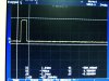
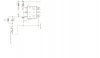
Here is my output for the circuit implemented using 555-LM324-2N2222 with Connection taken from 4.5V plug of the resister ladder.
Anomalies observed:
1. Even if I have implemented one Differentiator circuit, according to the manual pushing speed of the trigger switch the 1ms output duration is 'slightly' varying and some disturbances occur in the output pulse
Can I solve this by incorporating 74LS14 schmitt trigger inverters(2 Nos) in series with Microswitch.
2. Some noise like spikes are there at high level and low level of the output pulse. Is this is due to circuit or measurement setup ?
(0.5V voltage divisions from 5 to 0V are perfectly taking place with the use of resistor ladder having resistors of tolerance 0.01%)
Don't forget that a switch has contact bounce. When the switch is turned on then its contacts bounce and make and break over and over creating many pulses. A contact debounce circuit might be needed.
You forgot to say WHAT KIND oF CAPACITOR!!
If it is a film capacitor it is fine.
But if it is ceramic then the frequency will probably change when the temperature changes.
Don't forget that a switch has contact bounce. When the switch is turned on then its contacts bounce and make and break over and over creating many pulses. A contact debounce circuit might be needed.
Thanks Roff, I will check the performance of debouncer circuit and report here.
We have disused about the slew rate and rail in/out capacity of the op-amp to sync with 1ms pulses ranging from 0-5V in 0.5V steps. Can 2N2222 power transistor sync with voltage levels and timings ? Is there any better options ?
I dont want to connect a capacitor across a switch directly as the switch shorts out the cap when it is closed. That's not that good of an idea. However, with a small resistor like 100 ohms in series with the cap, all is well.
If I connect 100 Ohm in series with the capacitor across the switch, will it affect the Lower Threshold Point of Schmitt trigger inverter ?
Actually my 555 output at 10 V is greater than 5V and I used 50K POT to adjust it to the required level at load. For example take output from 4.5V leg of ladder and adjust the 50K POT to get 4.5V across the load. Without disturbing the set value of POT take output at all other voltage positions. One time adjustment is applicable for all voltage levels.
If I have exact 5V at top of ladder then this one time 50K adjustment is not required. For that I can use the cases you said, or 74121 / 74123 ICs as they can output exact 5V.
If I have exact 5V at top of ladder(by using 74121 instead of 555) then resistors of the ladder should be have 0.01% tolerance levels for equal divisions of this 5V.
My doubt is then the 50K in parallel with them could change the balanced condition of the ladder. Thus no equal voltage divisions takes place. Can I avoid this by placing 100K or 1M ohms (>> 1K ladder) in place of 50K without disturbing both ladder and the op-amp.
If I avoid POT and connect op-amp directly to ladder , then floating condition would be resulted between switching intervals of ladder outs.
the 555 requires a trigger pulse that goes below vcc/3. With a 10V supply, the pulse needs to be at least ≈7V p-p. You can't get that with the output of a 74LS14, which is only about 4V p-p. You need to use a CD40106, with the same vcc as the 555.
the 555 requires a trigger pulse that goes below vcc/3. With a 10V supply, the pulse needs to be at least ≈7V p-p. You can't get that with the output of a 74LS14, which is only about 4V p-p. You need to use a CD40106, with the same vcc as the 555.
This site uses cookies to help personalise content, tailor your experience and to keep you logged in if you register.
By continuing to use this site, you are consenting to our use of cookies.

")