vinodquilon
Member
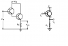
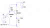
Consider the following Common Collector & Darlington emitter follower circuits,
CASE 1:
Let V(in) = 5V
Vcc(supply) = 10V
Emitter(load) resistance = 100 ohm
thus, V(out) should be 5V (following input)
Corresponding Load current will be 5/100 = 50 mA
CASE 2:
Let V(in) = 5V
Vcc(supply) = 10V
Emitter(load) resistance = 33 ohm
thus, V(out) should be 5V (following input)
Corresponding Load current will be 5/33 = 152 mA
Which source will provide this additional current requirement [Vcc or V(in)] ?
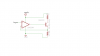
 . I got interchanged the collector and emitter.Thanks guru. Now I rectified the problem and the output follows input.
") output following the input with saturation occurs at 7.77V
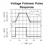
output following the input with saturation occurs at 7.77V