Continue to Site

Welcome to our site!

Electro Tech is an online community (with over 170,000 members) who enjoy talking about and building electronic circuits, projects and gadgets. To participate you need to register. Registration is free. Click here to register now.

  • Welcome to our site! Electro Tech is an online community (with over 170,000 members) who enjoy talking about and building electronic circuits, projects and gadgets. To participate you need to register. Registration is free. Click here to register now.

electronic switch to enable a camera to fire a flashgun

Status
Not open for further replies.

tony ellis

New Member
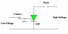
Modern camera circuits cannot handle the 400v that are present in old style flashguns. Rather than connect the flash to the camera sync socket, I want to use a low voltage switch that the camera can switch, which will then switch the flashgun(s). The advantage of using the old style flashguns is that a). they can be bought cheaply, and b). I can wire them to run off a led acid battery; I would be reluctant to do this with a flashgun costing £250!

I could use a slave flash, with a modern flash triggering the other flash through the slave. As I work outdoors, bright sunlight can saturate the slave and cause a malfunction, the range of the flash/slave is generally not that great, and obstacles between the main flash and slave can interrupt the operation.

My experience in electronics is limited to building a number of circuits from designs, using verro-board and pcb's.

Any ideas would be greatly appreciated.
 
This is intriguing me, are you talking about a flash unit that fits a standard 'shoe'? I can't imagine that a camera ever directly switched the '400v' potential because for a start, this charge is normally present across the tube throughout the entire charge / disscharge process - it is a third 'discharge' type electrode (on the tube) that normally initiates the discharge and obviously the flash (i.e. this smaller discharge overcomes the high resistance of the tube) - this will be from a smaller step-up coil and that in turn will be 'pulsed' by a transistor or similar.
Tell us more...?
 
interesting.

it sounds like an SCR might be suitable,
but i would like to hear more about the trigger mechanism.

As olly says, it usually worked an electrode to set off the
main discharge, the main discharge did not normally go
through the camera contacts.

John :)
 
Hi,

I don't know the arrangement that you are using,
but i am pretty sure that it does not include a
four hundred volt battery, this would be stepped
up from a lower voltage.

So there should be a lower voltage available in
there somewhere.

Use the lower voltage to operate the SCR gate.

Check the wiring, as it is quite likely that one
side of the flash has to be connected to common,
if so then come back and describe the wiring,
so as a suitable layout can be presented from someone.

This diagram is only to show that using an SCR is a
possibility, the layout shown may not be suitable.

Please give as many details of your setup as you can.

Regards, John :)
 

Attachments

  • Camera_contacts.jpg
    Camera_contacts.jpg
    6.7 KB · Views: 3,356
Hi, Thanks for the interest being shown in this item. With regard to the flash guns being used, these date back to the mid-70's, are "manual" guns (i.e. you calculate the required exposure by reference to the guns guide number), and do not include the thyristor circuit of later guns. I'm not sure about high and low voltage circuits within the flashgun, but am reliably informed that on these types of guns, the voltage across the camera switch can run up to 400volts. Several references to these high voltages are to be found on the internet.

In the old style cameras (Olympus OM1 and 2 are the ones I've used)that had mechanical contacts which were closed on firing the camera, we were always warned about linking more that one flash to the camera, because the high voltage across the switch could burn out the contacts in the camera.

What I'm looking for now is a low voltage switch that will trip the (up to four) flashguns without the voltage from these guns going anywhere near the switch contacts/circuit in the camera. I had originally thought that a solenoid type relay would do the trick, but the switching time is too slow.

So, what I need is a low voltage switch, running from say a 3v battery, that will trip when the camera is fired, allowing the flashguns to fire. I would prefer the flashguns to be fired independantly of each other, as different makes have different polarities on the sync cord, and two dissimilar guns can end up firing each other. If this is too complicated, I can run banks of "one manufacturer" guns.

The camera that I now use is a Canon 10d digital camera.

Again, thanks for your interest in this item.
 
If you want to control a high voltage from a low voltage source, use an optocoupler. They're perfect for this application.
Or is it a slave flash what you're looking for?
 
I have picked up the following off the internet - Sams Strobe. It seems to do what I want, subject to:

1 I can't follow the circuit - I'm used to following a verro-board layout, not a schematic.

2 If I wanted to fire 4 flashguns at the same time, with each gun being isolated from the others, where would the additional circuitry go.

I anticipate building the circuit into a project box, with its own 6v power supply ( actually taken from the 6v sealed lead acid battery that powers the flashguns); with an input cable coming from the camera hotshoe (the plug at the flashgun end of the cable being hard-wired into the project box; and with four 2.5mm sockets for the output. I will adapt four conventional flash cables by cutting of the normal camera plug and replacing them with 2.5mm plugs.
The attached article attached explains the situation with regard to the high voltages present on the trigger circuit of the old style flashguns.

Due recognition is given to SAMS STROBE as the source of this article, and anyone interested in the electronic circuitry of flashguns should look at this site. (Search on Sams strobe).

If anyone could provide me with a "verro-board" circuit for this project, I would appreciate it

Tony Ellis


SAM’s STROBE

Optoisolated Adapter for Older Flash Units to Low Voltage Cameras
(From: Brian L. Zimmerman (blz@home.com).)
Many electronic flash units can have a very high voltage between the trigger contacts that are shorted to trigger the flash. For example, the trigger voltage of the "Digi-Slave" DSF-1s flash unit being sold in 2001 for use with digital cameras (See for example, Slave Flash Products) measures 218 V fully charged. This would be dangerous to use on many modern electronic cameras such as Canon digital cameras which specify no more than 6 V.
This design adapts such a high voltage flash for use on a low voltage camera by using an optocoupler to electronically isolate the camera's contacts from the high voltage. It can then be triggered by the camera using the 6 volt supply from the flash unit's batteries, but also works at a lower voltage. The use of a triac optocoupler has the added advantages of using fewer parts than other optocoupler designs and can use the power from the flash's trigger circuit to fire the SCR switch instead of a separate power source.
The adapter circuit can be inserted into the lines inside the flash unit going between the flash trigger circuit and the flash unit's contacts as shown below. Since there are only 4 small parts in this circuit, there is a good chance that you can build it right into the available space inside the flash unit's case.
(WARNING: High voltage precautions apply here - be sure to safely discharge all capacitors!)
System connections

o--------------------- | ----------------------- (+)
Flash hot-shoe contacts | Flash trigger circuit
o--------------------- | ----------------------- (-)
\|/
Cut and insert
adapter circuit below

Flash adapter schematic

+---------------------+ R2
(-) o-----------(1)---+ +-----(6)----/\/\----+----o Flash Trigger (+)
| | OPTO1 | | 5.6K |A
To Hot-Shoe | __|__ ____|____ | __|__
(and camera) | _\_/_-> _\_/_/_\_ (5)NC _\_/_ SCR1
| | | | / | 400V,6A
(+) o---+ +---(2)---+ | | |G | K (RS#276-1020)
| | NC(3) +-----(4)---------+ |
/ | +---------------------+ |
R1 \ | Optotriac +----o Flash Trigger (-)
330 / | MOC3010
\ | (RS#276-134)
| |
o o
(+) (-)
To 6V Battery (Flash unit battery pack)

Parts list
1. SCR1: SCR, 400V, 6A, (RS#276-1020, $1.29, TIC106D, etc.).
2. OPTO1: Triac optocoupler (MOC3010, RS#276-134, $1.99)
3. R1: 330 ohm Resistor.
4. R2: 5.6k ohm Resistor.
RS# indicates Radio Shack part numbers. Total cost (October, 2001) is $3.75.
Operation
The camera shutter shorts the hot-shoe contacts, causing current to flow from the 6V battery through the IR-emitting diode at pins 1 & 2 of the OptoTriac. The current is transferred via light pulse which switches on the triac at pins 4 and 6 of the OptoTriac which is powered by the voltage from the flash trigger circuit. Current flows into the gate of the SCR, switching it on and causing discharge of the flash trigger through the anode and cathode of the SCR. The 330 ohm resistor (R1) limits the current through the hot-shoe to about 18 mA, and the 5.6k ohm resistor (R2) limits the current through the triac to about 40 mA. You may need to use a different value for R2 for your particular flash and SCR, since this is based on a 218 V trigger voltage. The triac can handle a larger current (1.2 A peak), but SCR's typically only use a small gate current for triggering.
Note
The circuit with component values shown seems to work reliably (at least so far) for this particular combination of Canon digital camera and slave flash. Others may be quite different. Some info can be found at Kevin Bjorke's: Non-Canon Strobe Page with a List of Trigger Voltages. Just knowing the trigger voltage isn't really enough information as it doesn't imply anything about the available current. Adding an input buffer using a transistor or CMOS gate would eliminate this as a concern.
SCRs and triacs should be driven hard when they are controlling high current sources to make sure they turn on quickly and minimize time where they are passing significant current with a significant voltage drop. The optotriac's output is current limited so this isn't much of an issue. However, the SCR discharges the trigger capacitor through the trigger transformer and this could amount to several A switched in a few microseconds. A gate current 10 to 20 times the minimum spec in the datasheet is recommended so long as this doesn't exceed the maximum rating in the datasheet. In any case, the worst that will happen is that the SCR will fail or become unreliable after running with marginal gate drive - no great loss considering its cost.
 
Hi Tony,

I had a look through your post,
and i think this is the page that you refer to:
http://www.carlmcmillan.com/images/Optoisolated_Adapter.GIF

i wasn't able to be sure of the other page, 'Sam's Strobe'
i couldn't find it for certain.

Anyway,
just in case you aren't sure about opto-coupling,
here it is used to operate the triac without touching it.
There is a small gap between the little light and the
light sensitive triac, so the signal is isolated from the
triac. This is called an 'opto-triac'

Because the contacts on the camera are isolated from the
flash unit, this is why a separate battery is required.

This separate battery only has to supply the triggering
signal and can be quite a small battery as its normally only
an LED that has to light to operate the opto-triac.

Mr Zimmerman recommends that the triac is driven hard to
minimise response times, so i suppose you should make sure
that the led in the opto-triac does not appear dim, the
series resistor controls the current through the LED, but
don't make it more than the manufacturers rating. The life of
an LED can be very much reduced if they are made to pass even
a little more than their rating.

Personally i would not have thought that it would make any
difference to the triac so long as it worked. But i would be
guided by Mr Zimmerman as he seems to think it does.

You can check the ratings and figures on line by looking up
the opto-triac details of the one you have.
When going to get the part, ask at the shop for an opto-triac
that will handle the voltage and current you need, rather than
looking one up, then trying to get it at the shop.

On that page there is also a schematic gif:
http://www.carlmcmillan.com/images/Optoisolated_Adapter.GIF

This shows on the left side,
the camera contacts and the resistor which limits the current
to the LED.

I don't know why he has used an opto-triac to drive an SCR.
Maybe he couldn't get an opto-triac rated for the job,
or maybe the smaller ones are quite cheap.
Anyway the circuit looks perfectly ok to me.

To transfer to vero-board.
Personally, i would make the assembly just thrown together
as a hedgehog without cutting any of the wires short on the
new components, soldering them together at full length, in
a bunch then check that it works as it is supposed to do.

Then i would cut all the components off with my side cutters
leaving as much wire on as reasonable, and poke them into the
veroboard, one at a time. Keeping track of what bits connect
to where. I have a small battery hand drill which i use to
make the 'breaks' in the vero-board where i want them.

When assembled, i would check its operation again, and if all
is well, i would cut the vero-board off with a hacksaw, and
probably file the edges neatly.

Some people like to draw things out, and lay it all out by
drawing it before they put the bits together.
I find that when putting components on to vero-board
sometimes the wires fold down nicely at some hole spacing,
so thats where i put them. Sometimes a resistor will fit
better 'standing up' than 'lying down' so it gets put where
it fits best. Just play about with the bits till you're
happy with it, and happy with the circuit connections.

Heres a bit about the opto-triac in that drawing,
http://www.web-tronics.com/moc3010.html
As you can see, it has six legs and fits on standard veroboard.
Try not to linger when soldering it in, i usually position a
damp rag to take most of the heat, i know they are sturdier
than they used to be, but i still like to be careful.
They are listed on that page as sixty cents.

I got your PM asking for clarification on this project,
i hope this covers what you need to know, but i am still a
bit unsure of what bits you are not clear about.

If theres anything else, just ask and me or someone else
will try to put you right.

Best of luck with it,
John :)
 
some answers and some questions

I was looking through the posts for some answers on an idea that i've got (i'll get to that in just a bit), and I must say this post was quite interesiting.

Any wa, it's true that most modern cameras can't support the high voltages that older flashes put out on their contact terminals. At most some will still support up to 250 volts. Thing is they normally trigger the external flash by shorting the flash terminal contacts , either mechanicly or electonicly.

so the use of an scr could be (and is a solution) as long as you have some sort of power supply to be able to trigger the scr's gate. the terminals on the camera will indeed need some sort of voltage on them to get a current flowing on triggering to trigger the scr and therefor the flash...

I've done something simmilar building a slave cell. its an optotransister conected to an scr. It really simple and works ok indoor and outdoors in lowlight. I found the schems for this type of circuit and they all had a filter, to eleiminate the signal (dC?) from ambient light, but that never worked. A few mods and its workin ok.. well not as ok as i wish it would, since its only good at late evening/night outdoors. But it works off the flashes trigger contacts. if you would like to see the cicuit I guess i could post it up.. i'll have to draw it out or something. really simple thing....

Anyway, what I've been thinking of, I'll probablly start a new post, is if anyone has tried or is thinking of making digital transmitters. I'm thinking of using this type of solution. They can be made for quite a low price.. I 'mean the ming TX-99 transmiter costs 10 bucks... and anything else you add is still cheap... better than spending 200 bucks on a pro system.. well at least while i'm broke..hehe

Yeah.. I'm gonna start a new post....
 
Status
Not open for further replies.

Latest threads

New Articles From Microcontroller Tips

Back
Top