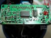
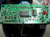
From the measurements, even though you weren't able to follow the board to get one of them to really confirm things, it seems like a pull-up input where the button pulls the input down when pressed. That measurement is measuring the resistance when the unit is unpowered between the 2.8V side of the switch and the regulated power supply (which should be 2.8V or somewhere around there...probably 3.3V). But you seem to be unable to find it. You might be able to find it by measuring the pins around the most prominent ICs relative to ground and see what the highest voltage encountered is. What you really want is the regulator which might be that IC with the 4 pins (one large one on the left, and three small ones on the right) to the bottom left of the central IC.
It might be debouncing or detecting the edge sometime after power up which would make the hardshort not work because otherwise a hard short should do the job for a pull-up circuit. If the unit is unpowered, and you hold the button while powering it up, I assume it does not react at all? That should be the same thing a hard short across the switch.
So if it was looking for an edge, placing a capacitor across the switch should do the trick. Holding the charge isn't a big issue since you can always put a high resistance (100k) value across the capacitor as well which will slowly drain it empty when unpowered. But if the circuit still isn't reacting to that, then it could be that the rising edge that it is looking for is too slow. Hmmm.