Continue to Site

Welcome to our site!

Electro Tech is an online community (with over 170,000 members) who enjoy talking about and building electronic circuits, projects and gadgets. To participate you need to register. Registration is free. Click here to register now.

  • Welcome to our site! Electro Tech is an online community (with over 170,000 members) who enjoy talking about and building electronic circuits, projects and gadgets. To participate you need to register. Registration is free. Click here to register now.

Electromagnet Control

Status
Not open for further replies.

willeng

Member
Hi everyone,
I have a very old small scrap yard oil filled electromagnet about 12"- 300m diameter that I need to control the strength of.
I have a small crane on the back of the truck I had for my workshop & want to fit the electromagnet to it to enable me to be able to clean up several tons of steel scrap I have laying around, it's a must do job & the only way I can do it.
I want to control the strength of it rather than just have ON-OFF as with just ON-OFF control the thing will be to strong & dangerous, if I can adjust it, it will make it much safer to use & it won't get as hot.
I don't want the thing that strong it wants to lift the steel tray off my truck either.:(

The electromagnet was powered by a 12v DC generator which was old & not working when I bought the lifting magnet & was sold as scrap by the previous owner.

This is a learning project as well & I was thinking about using an arduino to control the magnet with Mosfets & PWM.
The magnet is rated at 12Vdc & 75A.
I have a good 12Vdc 100A supply from an old charger that I can use or a couple of big 12V batteries if away from a power source.

The questions I have are:
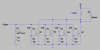
When triggering the gates of the Mosfets IRF3205 which I will attempt in Parallel configuration, is it best to use some TC426CPA Ic's & trigger the gates all individually with these gate drivers at the same time?
I have some of these chips on hand.

Or is it better to trigger all the gates together in series from one gate trigger driver, say a suitable transistor configuration?

Or can the TC426CPA chips be paralleled to trigger the Mosfets all at once in series from the same single trigger pulse?

Sorry for all the questions but I just need to have a good setup that will work & not fail.

Cheers
 
The gates are triggered all at the same time. You typically put a small resistor in series with each gate, just as you do with LED's, to balance the current and dampen oscillations ("ringing"). Those resistors are seen from the driver as being in parallel. Thus, 4 mosfets x20 Ω each will look to the driver as just 5 Ω. I built a couple of drivers for as large or larger inductive loads with similar and/or identical mosfets and used a dedicated IC for the gate driver and about 15 Ω per gate.

John
 
Hi jpanhalt thanks for the quick reply,

Yes, the gates are all triggered at the same time, do I trigger all the gates say on four Mosfets in parallel with a "single gate driver pulse" or is it best to have "four individual gate pulses", one to each Mosfet gate all triggered at the same time?
I am just a bit unsure about how much current is needed to make sure the four Mosfets are turned on quickly.
Basically is one output pin from the TC426CPA chip enough to trigger all four Mosfets ON or is it better to use two TC426CPA chips & have four outputs to trigger the four gates individually at the same time.

Cheers
 
Of course, how quick is quick? For an electromagnet, you will probably be at 20kHz or less (of you can stand the noise). I was a little above that threshold. But still 20 kHz is not "quick" by some measures.

I used the LT1158 (http://cds.linear.com/docs/en/datasheet/1158fb.pdf) to drive up to 5 similar mosfets in parallel. That was more than 15 years ago, and the drives are still working. Be sure to include a gate turn off resistor. I once started in an unknown state and blew a mosfet. I suspect one could use separate drives, but I don't see the real need for doing that.

I did not use a sense resistor as shown in the data sheet.

John
 
Hi jpanhalt,
Yes, I see what you mean, thanks for the data sheet & the info.
I'll try to draw up a schematic & post it once done before trying it out.

Thanks again
Cheers
 
You most likely will have to reverse the DC at turn off, as is normal with scrap yard cranes, this avoids small pieces of scrap kept attracted by residual mag.
Yard cranes are typically full-on control, no PWM.
Max.
 
Hi Max,
Yes, that is something I didn't think of ?
Ok, so if I have this correct, do I need a H Bridge circuit to do that as with reversing DC motors & just apply the reverse polarity for a short time ?

Or is there an easier way to do it maybe?

Thanks for the suggestion.
Cheers
 
Forgot to add the attachment!

Is this circuit basically what I require, drive circuit not included or the H Bridge if required now.

Cherrs
 

Attachments

  • Circuit.PNG
    Circuit.PNG
    20.5 KB · Views: 219
I have been trying to understand the Datasheet for the Mosfets & in particular the IRF 3205 which I wanted to use.

Could I get some help with this.

Datasheet attached.
I am a bit confused with this at the moment.

On page 4, Fig 8 is the Maximum Safe Operating Area graph, am I correct in saying that this Mosfet at 12V maximum will take about 7A only safely?
Am I reading this correctly?

Also, the Pd@Tc =25 °C is 200w obviously but above in the description of the Mosfet it says Power Dissipation of approx 50W.
This is due to the operating Temperature--Yes?

But then it says Id@Tc = 100°C the continuous Drain Current Vgs@ 10V is 80A
Could someone help me read this datasheet correctly so I know what I am looking at?

I need to work out how many Mosfets I require to do this job safely & reliably.

Cheers
 

Attachments

  • irf3205.pdf
    97.8 KB · Views: 140
I agree that figure is a little confusing unless you realize what the variable plotted on the X-axis is. In other words, Vds is not the supply voltage per se, it is the observed voltage drop across the drain-source given various Rds(on) conditions (i.e, Vgs). The mosfet is being operated in the linear region as opposed to the saturated region (mostly horizontal lines). Vds is the current times the apparent resistance of the mosfet (Rds). This note from Fairchild describes what the SOA means in more detail than that datasheet does: https://www.fairchildsemi.com/application-notes/AN/AN-4161.pdf

I hope this figure helps understant the two modes of mosfet operation:
upload_2016-2-2_5-44-34.png


In the linear region, note that as current increases, the drain-source voltage increases virtually as if the mosfet were a passive resistor. For example, with just 2 V gate-source, the Rds resistance is high, so a small change in Ids causes a large change in Vds. NB: I am using the terms dependent and independent variable rather loosely and without regard to how the actual experiment is performed. The heat produced is I^2R and that is a controlling factor. The description in the Fairchild note is more complete. You will want to design your device for working in the linear region with a 10 Vgs so the device is fully turned on.

As for the turn-off resistors, I only used one for the 4 mosfets in parallel. Your driver may not even require that resistor. I agree with Max that you will most likely be working full on and full off most of the time. The need to reverse is interesting and makes sense.

John
 
If you only want mag strength something less than rated, why not just lower the supply voltage supply level to some suitable level.?
Max.
 
Hi John,
Thanks for the explanation & the datasheet both of which I will have to read & study correctly to understand, I will take the time now to work it out.
I see what your saying with the turn off resistors, I was of the opinion that these were best left until the circuit is made & tested to see if they were required.

Yes, everything is a little confusing when I am not sure how to read the datasheets correctly & or don't have the experience but in saying that the learning process I find very interesting & it helps with things.

Cheers
 
Hi Max,
What you say of course makes sense & I agree but for the reasons of wanting to learn about controlling things & actually being able to accomplish things is a big part of life now.
I find it all very interesting & like to challenge myself trying to get a handle on what I am doing & what I don't know about.
It keeps me busy & I see a need now & in the future of having a few automated things around to help with day to day life.

I guess what I am trying to say is that challenging some cognitive issues I have now is the best way I have to deal with them , if that makes sense?

Cheers
 
How about rigging up another alty on the truck just for the magnet, and drive its field with pwm from the 'duino, a 80a alty only needs 7 or 8 amps for its field, this way your neither stressing your trucks electrical system, nor dealing with super heavy currents.
Theres no reason not to have a pot to control the magnets strength, and arduino is overkill, a tl494 would do the trick.
To kill any remanence and make sure everything falls off th emagnet on switch off maybe you could use a starter solenoid or something to apply ac from the alty to the coil.
 
As someone who has worked around the big 240+ VDC 50+ amp scrap yard crane electromagnets and controllers for years I have to say you are way over complicating what should be a simple process.

First off a small amount of variable resistance inline with the electromagnet like a large 500 watt 1- 2 ohm rheostat would give you a more than satisfactory power control over the unit.

For dropping you don't actually have to reverse the power polarity either. Simply opening the circuit and letting the electromagnets own field collapse through a free wheeling diode and a 1 - 1.5 ohm 50 watt resistor in parallel will give you a nice clean drop every time. ;)
 
Last edited:
All commercial mag controllers on such as fitted on Ohio Locomotive Crane rail crane products use reverse power for clean drop, they either use Hubbel or Square D magnet controllers.
Max.
 
Yes I am familiar with those designs and have made solid state units of my own design that have been in service for years without problems with dribbling and not needing to do the current reversing function to get a clean drop.

I know it works. It's simple electromagnetic field collapse physics. ;)
 
Hi everyone,
Thanks for the suggestions, much appreciated!

dr pepper, yes an alternator would do the the job, I have controlled the field winding's on some other things in the past & have several big Prestolite alternators that I could use.

tcmtech, I understand that a simple Rheostat would work without problems & it's very easy to setup & yes what I propose to do is over complicating the simple control of the magnet.

The reason I want to make a low voltage high current controlled supply is not just for the lifting magnet because there is only a few days work that it is needed for, cleaning up the scrap steel.
The main reason is that I need a good controllable higher current power supply as suggested because I don't have one & could use one for many things in the future so I thought this was a good opportunity to learn more about things, including PWM, Mosfets, Programming etc etc & kill many birds with the one stone.

It is a good project & something worthwhile that I can use for years to come.

After scrounging around yesterday, I have found what I think will make a respectable high current supply, I will draw up a schematic & post it to see if I am on the right track.

Thanks again for the suggestions.

Cheers
 
If you want something quick and temporary to control power use some seriesed & paralled headlight bulbs as dropper resistors, the good thing about these is you get a kick at switch on of higher power due to the cold resistance.
 
Status
Not open for further replies.

Latest threads

New Articles From Microcontroller Tips

Back
Top