Continue to Site

Welcome to our site!

Electro Tech is an online community (with over 170,000 members) who enjoy talking about and building electronic circuits, projects and gadgets. To participate you need to register. Registration is free. Click here to register now.

  • Welcome to our site! Electro Tech is an online community (with over 170,000 members) who enjoy talking about and building electronic circuits, projects and gadgets. To participate you need to register. Registration is free. Click here to register now.

Electro magnet

Status
Not open for further replies.
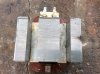
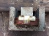
After reading your posts I have decided to go with a microwave transformer winding and field as in the photo.
Having used the transformer as a magnet which was not to bad the leads connecting to the battery did not get hot and the transformer was cool.
The winding wirer is 1.1 mm in dia and the number of turns is 208 and the restance is 1.9 meg omes.
I would like to increase the magnetic field .
Can this be done removing 4 turns on the windings.
I am very great full for your support.
 

Attachments

  • image.jpg
    image.jpg
    1.4 MB · Views: 160
  • image.jpg
    image.jpg
    1.2 MB · Views: 193
The winding wirer is 1.1 mm in dia and the number of turns is 208 and the restance is 1.9 meg omes.
I would like to increase the magnetic field .
Can this be done removing 4 turns on the windings.

Um what?

You may want to read up on the principle of Ampere Turns when it comes to electromagnetic forces.

Once you know your turns count and the current going through the wire you can figure out your ratios of magnetic force to wattage used.
 
Les:

Yes I think your right, my experience with wound components is more on the smps side which deal with ac.
Wouldnt the device need a magnetic shunt to operate on ac quietly and at reasonable efficiency?

TCM:

I wonder if the op has mixed up meg ohms with milli ohms.

Greg:

This is a solenoid force calc, I assume you understand ohms law and are able to work out required resistance for current flow.
I dont know if a transformer with the end cut off is a solenoid, I seem to remember a solenoid being a cylinder with wire wound on it, what you have is effectively a solenoid with the end split then wrapped around itself, so the calc may not be accurate.

https://www.daycounter.com/Calculators/Magnets/Solenoid-Force-Calculator.phtml
 
Last edited:
For more magnetism, wouldn't finding another microwave transformer of the same size and then take its primary winding and add it to the E-core and wire in series, work? When connecting the newer coil to the first watch that you keep the winding's in phase.
 
That would give the same strength magnetic field but only consume half the current. Twice the resistance so half the current. But as there will be twice as many turns the magnetic field will be the same. If connected in parallel it would give twice the magnetic field (Assuming the core did not saturate.) but it would take twice the current.

Les.
 
I do not think it would make any significant change to the magnetic field strength. I do not know this to be a fact so wait for some more replies.

Les.
 
Because your running at low voltage you might be able to make a tap by sanding the outer insulation off the windings and solder on a wire, if you can find a point with the correct resistance you'll be able to do this, finding a point with less resistance will increase current.
I agree with les on shortening the core not making much diffrence, you'd just be shortening the magnetic path length, which will only have a small effect.
The core you used has laminations which are insulated from each other, chopping the end off has probably shorted them all togther, that probably isnt a problem either if your running it off dc.
 
I don't think tapping down the winding will give a stronger magnetic field. If you tap in at half the number of turns then the current will double. (As the resistance is half.) But you now have half the number of turns so the product of the number of turns times the current will be the same as before.

Les.
 
Yes,
There will be a point where everything works as well as it can, the o/p isnt looking for perfection.
 
The core you used has laminations which are insulated from each other, chopping the end off has probably shorted them all togther, that probably isnt a problem either if your running it off dc.

Many microwave oven transformers have a weld bead across the laminations tying/shorting them together from the factory.
 
I think the reason the weld does not cause a problem is that it only shorts one edge of the laminations together (On 2 of the 3 legs of the "E") As a result it does not create a shorted turn around the magnetic path.

Les.
 
I am looking at setting up 7 of the transformers.
Connecting up 2 of the transformers with the same resistance in the windings.
Connecting 1 transformer to power supply 12v DC and connecting one transformer the reading is 8 v 6 amp
Then connecting 2 transformers in parelell the Voltage goes to 6v 6 amps but the second transformer is weak in the magnetic field.
Can you explain this
 
Hi Gregory,
Your last post is not very clear as to what you are doing. This is what I think you may be saying. You have a 12 volt DC power supply (Which presumably give 12 volts off load.) When you connect one transformer to the supply its output voltage drops to 8 volts and the current through the magnet (Modified transformer.) is 6 amps. (Which shows that the winding resistance is 1.33 ohms. You then connect a second Magnet in parallel with the first and the voltage from the power supply drops to 6 volts but the output current from the transformer is still 6 amps. This means that the resistance of the two magnets in parallel is now 1.0 ohms. You have already said that the magnets have the same resistance. If that was true then the resistance of the two magnets in parallel would be 0.67 ohms. You must be overloading the power supply for it's output voltage to drop so much. (What is the current rating of the power supply.) What does not make sense is that in one case drawing 6 amps from the power supply drops the output voltage to 8 volts and in the other case also drawing 6 amps drops the voltage to 6 volts. The statement "I am looking at setting up 7 of the transformers." does not seem to have any relevance to the situation in the post.

Les.
 
The power supply has a 7 amps max .
I am making Magna bender with 7 transformers about 1 meter long but I require maximum magnetic field strength in all transformers.
Where am I going wrong
 
Your power supply is in foldback current limiting. With just one of your magnets connected to 12 volts it would draw 9 amps. (You need to learn some basic electrical theory. Ohms law and power calculations.) To run 7 of your magnets from 12 volts would require 63 amps. (756 watts.) I had not heard of the "Magna bender" so I Googled it. I found out that it takes about 2.3KW I suspect the magnetic design is going to be far better than you or I could design so I would expect a DIY one to take more power. I do not think you will succeed with this project.

Les.
 
If I make a iron Cor with one winding would this be a better properitation
Making the Iron field is no problem
 
At 63A a huge car battery would last about 15 minutes and its electrolyte might boil away.
 
Hi shortbus=,
That's an excellent link. I don't know why so many people post question on forums like this before using Google to find information first. I found this link.
https://aaybee.com.au/Magnabend/Magnabend History of Development and Manufacture.html
which shows the prototype and found the power requirements on a sellers website. I think all the information that Gregory needs to build one is on the website that you found. Proof of the power of Google.

Les.
 
Status
Not open for further replies.

Latest threads

New Articles From Microcontroller Tips

Back
Top