Continue to Site

Welcome to our site!

Electro Tech is an online community (with over 170,000 members) who enjoy talking about and building electronic circuits, projects and gadgets. To participate you need to register. Registration is free. Click here to register now.

  • Welcome to our site! Electro Tech is an online community (with over 170,000 members) who enjoy talking about and building electronic circuits, projects and gadgets. To participate you need to register. Registration is free. Click here to register now.

ECG amplifier

Status
Not open for further replies.

sapphire_blue

New Member
Hey guys,

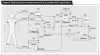
I am trying to build an ECG amplifier with 3 electrodes. I am using AD620 as the instrumentation amplifier. I built the ECG circuit shown in this link on page 15: https://www.electro-tech-online.com/custompdfs/2009/01/AD620.pdf
with a few modifications made to the right-leg driver circuit.

I didn't use C1 and R4. My right-leg driver circuit just has R1 = 50 Ohms and R2=R3=100 Ohms and LM741 as the op-amp. I removed C1 and R4 because I wasn't really sure why they were there. Our circuit is not working, all we see is noise. We placed two electrodes on the chest and one on the right wrist. Could someone please help me with this? Is there a better ECG circuit or could someone explain what exactly the right-leg driver circuit should have?

Thanks!
 
C1 and R4 are crucial feedback components, don't leave them out - and don't use a crappy 741, use the opamp they suggest (741's are as low a spec as they come, pretty well).
 
How do I choose the values of C1 and R4?
Why do you want to deviate from the schematic values for any of the components? The values were selected for a good reason. Unless you really know what you are doing, you generally don't want to deviate from the given values.

You pick arbitrary values for some of the components (some of which are several orders of magnitude different from the assigned) leave out others, and then wonder why the circuit doesn't work. Is that really a suprise?

Use the assigned values, add all the parts back in the circuit, and then let us know how it's operating.
 
I'll be surprised if your circuit is working. R4 is a key part for the driver circuit. it's the feedback resistor of the amplifer circuit. without R4 the gain of the driving circuit is very low. 741 isn't a smart choice for applications like ECG. noisy, low open loop gain, low input impedance, high drift... The only virtue of 741 is it's price.
 
Last edited:
Hi, I also wanna build ECG amplifier. But may i know why the circuit amplify ecg signal first then only high pass filter the signal? Then, we need to amplify the ecg signal to a very high signal than the noise?
 
That's a ground reference.
 
The datasheet for the AD705 opamp shows that its max input offset voltage is less than 1/100 times the max input offset voltage of ordinary cheap opamps. Its gain is very high so an ordinary opamp will amplify its own input offset voltage and then be saturated.

The right leg driver cancels DC and low frequency common-mode voltages that both inputs pickup so that the instrumentation amp is not saturated. The 24.9k resistors must be matched.

The highpass filter is used at the output so that a DC offset voltage is not amplified. Of course a lowpass filter is also used to reduce noise.
 
regarding leg driver

please explain the working of ad 705 connected to leg driver .what is its function ?
what are the role played by the R1 and c4 ?
basically what leg driver will do?
 
Here is another ECG circuit that uses the right leg for cancelling the DC and very low frequency common-mode voltages:
 

Attachments

  • ECG circuit.PNG
    ECG circuit.PNG
    42.3 KB · Views: 23,717
Opamp A5 is a buffer with a very low output impedance for the 2.5V reference voltage.
 
...which is serving as the ground reference voltage for the signals. Your power supply ground looks like -2.5V (or -3V in the original circuit) to the amplifiers.
 
I've been testing out various parts of the circuit on their own since I still don't have the overall circuit performing correctly...

I've been having a look at the integrator part of the circuit and I've built it stand-alone to test it. This is the setup I have:

**broken link removed**

Now all the theory I've come across suggests this should behave as a low-pass filter, and indeed this is the behavior I see when I test the circuit, however in the overall schematic of the ECG Amplifier it seems to be suggested that it should behave as a high-pass filter to eliminate baseline wander...

Can someone please explain how the setups differ?

Thanks...
 
The integrator is a triangle-wave generator when it has a comparator at its input that has feedback from the output of the integrator.

When the comparator senses that the output of the integrator is low enough then its output is low into the input of the integrator which makes the integrator make a rising ramp at its output. When the comparator senses that the output of the intergrator is high enough then its output goes low and the integrator ramps down.
 
For the attached RLD ... the 24.9k (R3 and R2) resistors are used for what and they do not in any way affect the gain right of AD620 right? Secondly, can R3 and R2 can be any values ... like 290 ohms?
 

Attachments

  • untitled.GIF
    untitled.GIF
    12.9 KB · Views: 6,066
Status
Not open for further replies.

Latest threads

New Articles From Microcontroller Tips

Back
Top