Continue to Site

Welcome to our site!

Electro Tech is an online community (with over 170,000 members) who enjoy talking about and building electronic circuits, projects and gadgets. To participate you need to register. Registration is free. Click here to register now.

  • Welcome to our site! Electro Tech is an online community (with over 170,000 members) who enjoy talking about and building electronic circuits, projects and gadgets. To participate you need to register. Registration is free. Click here to register now.

Easy way to get bandpass filter?

Status
Not open for further replies.

Mr RB

Well-Known Member
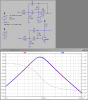
Hi, I have a simple application which needs a crude bandpass filter, to pass signals between 5kHz to 10kHz.

The bad news is that I can't use opamps as PCB space is at a premium, and wanted to do it with minimal parts (preferably just discretes or maybe 1 transistor etc) for cost issues too.

The good news is that the incoming signal is quite large, probably 5v peak to peak, and I only need about 200mV peak to peak output (into a high impedance audio input) so there is plenty of headroom for a passive filter.

It doesn't need to be that sophisticated, just to remove most of the guff below 5kHz and above 10kHz.

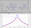
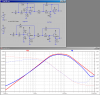
Options I am considering are overlapping lowpass and highpass passive filters, or maybe a low-Q LC filter centred on 7.5kHz.

I appreciate any suggestions. :)
 
Quantify "most of the guff". dB per octave is the usual way of describing filter rolloff.
 
I used TI's "FilterPro" to design the opamp version, and then substituted an NPN transistor and pull-up for the opamp. Looks like it may have some possibilities.
 

Attachments

  • Draft35.png
    Draft35.png
    26.6 KB · Views: 659
The problem I see with discrete inductors/caps, is that the cascaded sections interact with each other, with the source impedance AND the load impedance.

If you know the source and load impedances, and they are predictable and don't vary much, you may probably get away with an all-discrete solution. Otherwise, MikeMi's circuit proposal may be your best bet, although if your load impedance is low, an additional emitter-follower transistor may be required...
 
Last edited:
Hi there,


I like the transistor idea best i think, or the op amp if that is possible.
We really need to know the input and output impedance too though.

Here is another idea that is totally passive...

Requires two 1mH coils, two 0.45uf capacitors, and a 10 ohm (or so) resistor...

One coil is wired in series with one capacitor, and that is connected between
input and output. The other capacitor is connected in series with the 10 ohm
resistor, and the other coil is wired in parallel with that combination, and
that parallel circuit is wired from the output to ground.
What this forms is a series/parallel resonant network that has a relatively flat
bandpass region between approximately 5kHz and 10kHz.
The 10 ohm resistor value is made actually equal to the series resistance of the
coil (and both coils are the same part number) so it may have to change from
say 1 ohm to say 20 ohms, depending on the manufacturer.

We dont really know what your input and output requirements are so it's
hard to say exactly what will work for your application, but the above is
an example of what you can do with passives.
We would also have to know your output impedance and required new
output impedance too.
 
Last edited:
The bad news is that I can't use opamps as PCB space is at a premium, and wanted to do it with minimal parts (preferably just discretes or maybe 1 transistor etc) for cost issues too.

Don't you think that by using opamps in modern small outline packages, you will be able to implement an opamp filter a lot smaller than using discrete inductors?

Opamps can be obtained in really small packages.
 
Thanks a lot for the responses! :)

The source impedance is low, it's taken from an amplifier output through a lowish resistor, so I expect in the hundreds of ohms, maybe less and the source signal is large, 5v peak to peak.

The load impedance is very high, it is going into a PIC comparator pin, so is probably in the hundreds of kohms at these frequencies and only needs to be 200mV or so amplitude.

As for "dB per octave" it is not that critical as I had planned to bias the comparator to ignore signals below X amplitude, so in effect this will give infinite dB cut once the signal is below X amplitude. Maybe 6dB per octave, 12 would be better but may be uinreasonable.

For low frequencies it needs to reject mains ie 50Hz, 100Hz and probably 200Hz (400Hz?) harmonics, and at the high end it needs to reject all line noise hiss, electrical noise etc.

I like Mike's circuit, especially as it can be done with a transistor, but it is still fairly high Q, what would be ideal is that the entire range 5kHz to 10kHz is allowed through at equal amplitude, and anything outside that range is cut. It needs to look more like a table and less like a thumbtack. ;)

It's one of those deals where everything is a compromise, I can get a better filter with more PCB and parts cost, or a worse filter but using much more complex decoding software, etc. Hopefully somewhere there might be a working solution near the middle.

Thanks with the parts suggestions, MrAL 1mH coils would be too big and The Electrician yes i am keeping SMD opamps in reserve if nothing else pans out.

Currently I am leaning towards 2 RC filters in series, a highpass with pole about 12kHz and a lowpass with pole about 4kHz, (guessing values) hopefully with 5v going in I might still get something 200mV out in the target range 5-10kHz. It's a little nasty but maybe it could work with some software to cover its weaknesses.
 
Hi again,

You can get 1mH coils same size as other coils, about the size of a 1/2 watt
resistor for signal levels.
With those values, you do get a 'table' like response, where you get a sloping
front and sloping back, but between 5 and 10kHz is very flat.
 
Last edited:
There is a long lost technique that works well for these situations. It's called image parameter filter design. It cascades half sections and full sections. ITT handbook used to cover the topic.
 
Sallen-Key 2 pole Butterworth High-Pass cascaded with Low-Pass. I converted the unity gain opamp to an emitter-follower, which is almost unity gain...

Note, it is ac coupled, so you cannot rely on the dc level info....
 

Attachments

  • Draft35.png
    Draft35.png
    41.2 KB · Views: 544
Last edited:
Yet another, this one is a 2-pole bandpass with a Q of only 1. Also converted to using an NPN transistor.
 

Attachments

  • Draft35.png
    Draft35.png
    32.5 KB · Views: 309
Thanks again everyone for the ideas and especially Mike for the schematics and sims.

At the moment the best shot looks like Mike's last schematic, it's only 2R and one transistor more than my 2R 2C kludge and better performance. And all parts I can use 0805 + SOT23 which can be spead around the PCB so it's pretty good for size.

I've got some hardware arriving later this week so I'll fiddle with that first and hopefully get some more clearly defined requirements which I will post then. Thanks again!
 
I used TI's "FilterPro" to design the opamp version, and then substituted an NPN transistor and pull-up for the opamp. Looks like it may have some possibilities.
Mice designs MikeMI, they look great, while simple. The passive counterparts would be much bulkier.
 
Hi again,


Yes the LC filter requires two inductors which is a bit more trouble.

Here is why the LC filter looked attractive:
 

Attachments

  • LC-BP-01.gif
    LC-BP-01.gif
    8.3 KB · Views: 339
Help out a confused engineer here, why are we substituting transistors for opamps in these filters? I've never seen such a thing before.
 
The space for the circuit must be small.
A transistor has only 3 leads while an opamp has 8 leads.
Both perform exactly the same in the circuit.
 
Help out a confused engineer here, why are we substituting transistors for opamps in these filters? I've never seen such a thing before.
Afterall you need a gain block
a simple transistor makes circuit easy to make. It is Nice using OP amps and advanced components. MikeML has proved that it is possible to achieve the results with transistors even. Let us admire simplicity.
 
An elegant design is a design that properly realizes a circuit function with the minimum and simplest components. By this definition, MikeMi's circuit is elegant.

Of course, an opamp would provide an improved performance, which in more demanding application may be required. But the O/P's original post indicated that this is not a high performance application, and that space was its most important consideration.
 
Status
Not open for further replies.

Latest threads

Back
Top