Continue to Site

Welcome to our site!

Electro Tech is an online community (with over 170,000 members) who enjoy talking about and building electronic circuits, projects and gadgets. To participate you need to register. Registration is free. Click here to register now.

  • Welcome to our site! Electro Tech is an online community (with over 170,000 members) who enjoy talking about and building electronic circuits, projects and gadgets. To participate you need to register. Registration is free. Click here to register now.

EAGLE Tip of the Day

Status
Not open for further replies.

Speakerguy

Active Member
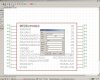
You can name active low input pins with EAGLE's inverting pin symbol.

Alternatively, you can have a line over the pin name so it looks like most data sheets have it and you don't have to use conventions like /EN for enable low.

For example, !MCLR!/VPP/RE3 typed in as a pin name will result in MCLR/VPP/RE3 shown on the device symbol's pin name but only MCLR will have a bar over top of it indicating active low.

Hope that helps! Feel free to pos rep me at anytime :)
 

Attachments

  • untitled.JPG
    untitled.JPG
    191.2 KB · Views: 911
Last edited:
Hi Speakerguy,

this method has just one minor advantage. If you name the pin you won't have the pad number on the schematic, which is normally used for trouble shooting. Doing that with the pin describtion requires a datasheet of the chip to know where you have to put your probe.
I prefer having both info of the device, pin name and pad name (number).To indicate an inverted input or output I use 0.12mm thickness and draw a horizontal line above the text using 0.635mm grid size and letter size of 1.4224 mm using the names layer. To make it look better I switch to grid size 0.3175 when everything is done and adjust the line length to the actual text length.

Hans
 
Status
Not open for further replies.

Latest threads

New Articles From Microcontroller Tips

Back
Top