Continue to Site

Welcome to our site!

Electro Tech is an online community (with over 170,000 members) who enjoy talking about and building electronic circuits, projects and gadgets. To participate you need to register. Registration is free. Click here to register now.

  • Welcome to our site! Electro Tech is an online community (with over 170,000 members) who enjoy talking about and building electronic circuits, projects and gadgets. To participate you need to register. Registration is free. Click here to register now.

Eagle Package problem

Status
Not open for further replies.

Wond3rboy

Member
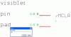
Hi, Here is the datasheet of a sensor having the package SOT23-6.I learned how to make a custom Eagle package from insturctables.com. The problem is that i cant understand the dimensions correctly.Heres my interpretation(most likely its wrong):

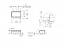
Horizontal Length=2.75mm

Vertical Length=1.45mm

Vertical Length(with pins)=2.6mm

Distance b/w centers of two pins=0.95mm

Horizontal Len: of pins=?

Vertical Length of pins=?

I cant even guess the above two!Please correct me and if i have missed any other important parameter then also point it out!:p
 

Attachments

  • datasheetsot23-6.pdf
    293.8 KB · Views: 270
  • sot23-6.JPG
    sot23-6.JPG
    33.6 KB · Views: 1,188
Last edited:
Go to ref-packages.lbr
The SOT23-6 is there.

John
 
Last edited:
For some reason its not in my Eagle Library.The ref-packages.lbr is present but when i search for it it turn up nothing.This has happened with some other components also.Is it because i am using it as freeware?I downloaded it again but the existing file is 3.24mb and the downloaded one is 3.23mb so i didnt overwrite it.Can you tell me what the problem is!
 
in version 5.2.0 it is called TSOC6.

If you prefer you might use my library.

The package was made using the attached data sheet. Yours is incomplete. (no soldering footprint)

Boncuk
 

Attachments

  • SOT23-6.zip
    993 bytes · Views: 379
  • SOT23-6.pdf
    168.5 KB · Views: 356
Last edited:
My version of EAGLE is 5.2.0 as well. In my version it is present as SOT23-6 and as TSOC6. When I got to the SOT, I didn't bother to look further down the list.

The libraries should not be different between freeware and purchased copies. I wonder whether the OP (or someone he got the program from) accidentally hit the dreaded drop button instead of the OK button when adding components?

One suggestion is to fresh install the freeware.

John

Edit: Just noticed the file size differences. Bigger doesn't necessarily mean better. I suggest re-install with the newest version.
 
Last edited:
in version 5.2.0 it is called TSOC6.

If you prefer you might use my library.

The package was made using the attached data sheet. Yours is incomplete. (no soldering footprint)

Boncuk

Thanks Boncuk.I downloaded it from ti.com but its a shame that it isnt the full data sheet.Thanks for the package you made.Appreciate it greatly.Also since you are 'the' PCB Guy around here i have one question:

Can i make double sided boards by using Eagle freeware?
I am planning to make a complete Junebug this vacation.

My version of EAGLE is 5.2.0 as well. In my version it is present as SOT23-6 and as TSOC6. When I got to the SOT, I didn't bother to look further down the list.

The libraries should not be different between freeware and purchased copies. I wonder whether the OP (or someone he got the program from) accidentally hit the dreaded drop button instead of the OK button when adding components?

One suggestion is to fresh install the freeware.

John

Edit: Just noticed the file size differences. Bigger doesn't necessarily mean better. I suggest re-install with the newest version.

I just reinstalled it.And got nothing.I downloaded it from cadsoft.de.Will downlaod a fresh copy now.Thanks
 
I downloaded a new copy and intalled it.The problem is that it doesnt show some libraries! I guess thats the reason i am not getting all the packages.What could be the problem?

And its not picking up Boncuks custom made library also!
 
Last edited:
The horizontal pin length from your diagram looks to be 0.3mm and the verticle length some 1.0mm, although thats not shown. Verticle pin length wouldnt be that critical I wouldve thought, dosent affect the layout.
 
Hi Abbas,

thanks for the flowers. :)

I'm just a perfectionist, nothing more but also nothing less. If I get a package "served" I normally check the truth before using it for a design.

(absolutely no drive to mess around with false dimensions of any part.)

If you want to use that library, containing nothing but a package I recommend to put it in your '.lbr' directory.

To create a device you must make a symbol first. Save the symbol with the pad numbers (I prefer pads instead of pin names and name the pins within the symbol for easier tracking in the PCB layout, which is also very useful when debugging a circuit.)

Use the symbol to create the device and assign the package (SOT23-6). Assign the pin numbers and you're done after saving the device.

BTW, there are some key dimensions in any component to be used:

The body size is of minor importance and can be negligated in most cases. It will result automatically using the correct pin spacing horizontally and vertically. Most important is the factory given soldering foot print which must be true for any deviation of outer dimensions of the part.

Draw the footprint first and add the outline of the package when finished. The more accuracy you apply the more likely the part will fit without measuring the dimensions physically. My selfmade minimum requirement is 1/100mm.

Kind regards

Boncuk


P.S. And of course you can make double sided PCBs with the free version, but restricted to a board size of 100X80mm (3.94X3.15inches)
 
Last edited:
The horizontal pin length from your diagram looks to be 0.3mm and the verticle length some 1.0mm, although thats not shown. Verticle pin length wouldnt be that critical I wouldve thought, dosent affect the layout.

But it does affect soldering a part in place properly. The pad size is determined by actual pin length and the surface left over to solder the place in part. (The solder pad must be longer than the maximum pin length.)

It won't do you any good to have a neat looking layout and when it comes to soldering you don't have any copper area where to connect the part.

Soldering underneath a part has some unwanted side effects. :D

BTW, all SMD parts are based on metric scaling (at least the body dimensions) . Switch to at least 1/20mm to find out the dimensions of pads and part body size.

Regards

Boncuk
 
Hi Abbas,

thanks for the flowers. :)

I'm just a perfectionist, nothing more but also nothing less. If I get a package "served" I normally check the truth before using it for a design.

(absolutely no drive to mess around with false dimensions of any part.)

If you want to use that library, containing nothing but a package I recommend to put it in your '.lbr' directory.

To create a device you must make a symbol first. Save the symbol with the pad numbers (I prefer pads instead of pin names and name the pins within the symbol for easier tracking in the PCB layout, which is also very useful when debugging a circuit.)

Use the symbol to create the device and assign the package (SOT23-6). Assign the pin numbers and you're done after saving the device.

BTW, there are some key dimensions in any component to be used:

The body size is of minor importance and can be negligated in most cases. It will result automatically using the correct pin spacing horizontally and vertically. Most important is the factory given soldering foot print which must be true for any deviation of outer dimensions of the part.

Draw the footprint first and add the outline of the package when finished. The more accuracy you apply the more likely the part will fit without measuring the dimensions physically. My selfmade minimum requirement is 1/100mm.

Kind regards

Boncuk


P.S. And of course you can make double sided PCBs with the free version, but restricted to a board size of 100X80mm (3.94X3.15inches)

I copied the symbol in the lbr flder and also updated it.Got nothing.Thanks for your tips on making custom packages.I will keep them in mind.I will now try installing Eagle in my laptop and see if it doesnt pose any problems(hopefully).This library problem is because of my computer rite?cause i downloaded a fresh copy from cadsoft.de.
 
What version of Eagle have you been using? What do you mean by, "got nothing?" Was the screen blank, or did you get an error message?

John
 
What version of Eagle have you been using? What do you mean by, "got nothing?" Was the screen blank, or did you get an error message?

John


The search turned up nothing. Sorry, no match!. Eagle 5.2 doesnt have any wonders too(not that i was expecting it to).The only thing i get by typing SOT is a SOT23 some LM IC.It gives the same result.
 

Attachments

  • Hear Tearing Frustration.gif
    Hear Tearing Frustration.gif
    14.1 KB · Views: 265
Why not just go to the library we directed you to and get it there?
Again, what version were you using before loading 5.2?

John
 
Hi Abbas,

I'm convinced you don't go the logic way when copying a package from one library to another.

If your PC doesn't write windows will come up with a severe error message like "disk full", "can't read from FAT" or similar messages.

You can't copy one library to another. Moreover you must copy and paste parts (components) from one to another.

Please follow these steps and I expect a success report only.

Open the library I posted and get the "package". Check if all necessary layers are active, 'pads' (layer17), 'tPlace' (layer21) and if necessary for SMT components also 'top' (layer1).

Group the entire package including the texts >NAME and >VALUE. Use the scissors symbol for "CUT" and hit the green traffic light next to the STOP symbol. When the green light extinguishes the package has been stored to the paste buffer.

Close that library and open the one you want to copy the package to. Select 'package' --> 'new' and type in the name "SOT23-6".

Next look for the brush symbol with a bit of yellow paint. Hit that and throw the package out of the paste buffer onto the screen. (with the XY-position centered on the package or a reference pad)

Hit save and you're finished. Opening the library again the package name should be contained in the list.

However the package is a lone package, not assigned to any 'device'.

Click 'symbol' and create a symbol of the IC you want to put into the SOT23-6 package. Do that the normal (personally preferred) way numbering the pads and writing the pin name into the box. Click 'visible' and activate 'pads'. If you do that before placing any pin on screen the pin displayed shouldn't have any fancy name attached to it like 'P$2'. See the screenshots for details.

Finish and save the symbol you've just created.

Next create a device, which must contain of a symbol and a package.

Click device --> new and type in the device's name, e.g. 'ABBAS-01' :)
Next 'ADD' the symbol you already have made and assign the appropriate package.

The device is now almost finished. However Eagle has no faint idea of how to assign pins to pad numbers. So next you must 'connect' pins and pads.

The example shown carrying the pin name /MCLR has to be assigned pad number1. You won't have to check the data sheet again if you use the method I described when creating the symbol. Just connect the same numbers like G$1 -> to pad 1 (G$1 is the pin name which Eagle assigns automatically if you don't explicitely give a pin name)

When pin and pad assignment is finished save your work with a new component ready to use in the schematic and board editor.

Regards

Boncuk
 

Attachments

  • visible.gif
    visible.gif
    4.9 KB · Views: 242
  • visible01.gif
    visible01.gif
    7.8 KB · Views: 214
Last edited:
Done that too.I guess the only thing remaining is to throw this dump(PC) away!

A PC is dumb from nature. In that case I suppose the misbehaviour is caused by the grey cells of the operator. (normally located between both ears :))
:D:D
 
A PC is dumb from nature. In that case I suppose the misbehaviour is caused by the grey cells of the operator. (normally located between both ears :))
:D:D
Thanks Boncuk.Me happy now!I guess the grey cells need some tuning so ealy in life:D

By the way: I tried the same thing to look for this in the ref-packages.lbr as said by Jpanhault.I couldnt find it there.So the i downloaded an incomplete copy?
 
So the i downloaded an incomplete copy?

That is virtually impossible to do and have a functioning program.

You have yet to identify what versions of Eagle you had and what versions you are trying to use now. What gives?

John
 
Status
Not open for further replies.

Latest threads

New Articles From Microcontroller Tips

Back
Top