Continue to Site

Welcome to our site!

Electro Tech is an online community (with over 170,000 members) who enjoy talking about and building electronic circuits, projects and gadgets. To participate you need to register. Registration is free. Click here to register now.

  • Welcome to our site! Electro Tech is an online community (with over 170,000 members) who enjoy talking about and building electronic circuits, projects and gadgets. To participate you need to register. Registration is free. Click here to register now.

Eagle cad connector problem can't hook up wires

Status
Not open for further replies.

mramos1

Active Member
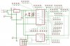
Bill (Blue room) got be all excites about the blackfly, I figured I would make a 18 or 8 pin PIC board to proto on. Just really learing eagle cad.

I dropped a 2x5 connector and it will not connect the pics to the connector
in the PCB mode? Any ideas?

EDIT: moved schematic to the end of this thread (corrected) saved some disk space.
 
Last edited:
will not connect the pics to the connector
in the PCB mode?
You need to do this in Schematic mode. Once you enable the PINS layer, (I don't know why this isn't the default :rolleyes: ) it will be easier to snap the Nets (connecting conductors) to the components. See attachment as per justDIYs post:
 

Attachments

  • eagle.gif
    eagle.gif
    15.5 KB · Views: 2,261
Thanks JustDIY and kchriste.

I just did not hit the little marks. Good to know about "pins". Learn about turning off routing lines today as well.

I figured single layer out as well. 1 = * and 16 = N/A. And save it for future boards.

I had a couple major error I fixed as well. Since I lined up all the port pins (GPIO to RB), then added ICD connector and short 2 of them to each other. (RB6 and RB7) :)

Triyng to get a single sided, 8/18 pin pic board with small proto area. For quick projects. ICD on the 18F88 and a programmer if nothing else.

My Grandfather is going to look at making it single sided. He no longer has Orcad, but pulled Eagle. He is a quick learner.

I made three tries at it, closer I came the worse the jumpers became. 3 jumpers, but they were jumper wires not 0 ohm resistors.

He is retired, but a PCB/mechanical man..
 
Did you design this connector schematic symbol/layout yourself, or was it a premade one? this kind of problem is common when you design the part with a different layout grid than the schematic you're trying to use it in. For instance, in schematics, you're usually using 0.1" grid and all your wires are snapped to it. If your part was designed with a smaller grid and then the finished symbol wasn't placed such that all the pins fell on the points of the default 0.1" grid, you get the type of problem you are experiencing, where the wires and the pads don't line up.

When I design the schematic symbols for new custom parts, I usually set the grid to 0.0125" (which is 1/8 of 0.1") and then set the "multiple" property to 8, so that the grid that gets displayed is 0.1", but I can still draw and position things on the finer 0.0125" grid; and then I can very easily make sure that I get all the connection points placed directly on the junctions of the 0.1" grid so I won't have any issues using them in schematics with default grid sizes.
 
sometimes its easier to rip out all your nets and start over ... when eagle gets cranky, it will merge nets and you'll end up with what look like separate wires but they belong to the same net!

also be sure to use NET command and not the WIRE command when drawing your schematic ... the netlist (made with nets) tells the autorouter connect A to B ... the wire command just creates signals, and will confuse the heck out of the autorouter (if you dont care about the autorouter, then it doesn't make much difference)
 
I got it all working as I mentioned. I just missed the pads little - on it. I went through it figured that would be more than enough.

I would like to find a more current PIC lib for Eagle. I am using a F84 as the F88 and a 509 as a 683..
 
I'd suggest taking the time to learn to make your own parts in eagle. it's really not hard, and it's usually fast enough that I prefer to just make my own whenever I need something, rather than searching for a premade library.

With that said, have you looked at the list of user-submitted libraries on the eagle website?

Unfortunately, many of the libraries on there only have a couple new parts in them, so you may have to piece a bunch together, which is part of why I stick to making my own... I blame eagle's poor library management system.
 
Evandude.

I looked, did not find 16F88 and if I asked them I am sure they would say use the 16F84, same pinout.. I could rename it and add the PGD and PGD etc.

That is what I will do, after I figure out how to make/edit a part. It really is just adding text to the pins and changing the part name.
 
it's not the same pinout. close though rx and tx are on different pins.

One thing you should do in the schematic editor is always keep the grid on .1" grid. Otherwise, you can't hook things up. It looks like that is what happened here. I use an alt-grid of .025" for moving names and values around but never do that for components.
 
I keep it at .1". Also, I hold ALT when I move the text and some lines, never on the parts. The ALT lets me move the text were I need it in PCB in smaller increments.

The problem was, I did not hit the pins in the right place, just adding it last minute in a hurry.

Going to lay this version out today. Sort of a quick project board.
 

Attachments

  • new11.jpg
    new11.jpg
    112.8 KB · Views: 2,218
Status
Not open for further replies.

Latest threads

New Articles From Microcontroller Tips

Back
Top