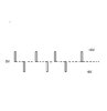
Continue to Site

Welcome to our site!

Electro Tech is an online community (with over 170,000 members) who enjoy talking about and building electronic circuits, projects and gadgets. To participate you need to register. Registration is free. Click here to register now.

  • Welcome to our site! Electro Tech is an online community (with over 170,000 members) who enjoy talking about and building electronic circuits, projects and gadgets. To participate you need to register. Registration is free. Click here to register now.

dual power supply CMOS

Status
Not open for further replies.

arivel

Member
Hello to all.
can you clarify something for me?
is it possible to use a dual power supply for the integrated CMOS logic gates?
I refer for example to those integrated with power supply voltage from 0-15V or from 0-18V. for example use a double voltage -6V + 6V
 
You can use +/-6V. I have used +/=5V.
There are several types of CMOS. Most switch at 1/2 supply. So on you -6V, +6V a 0=-6V and a 1=+6V and the part will choose 1 or 0 at about 0V.
Several of the SMOS "analog switches" work well with +/-6V. They play with opamps and audio well in this mode.
 
As long as the logic zero is -Vdd and the logic one is +Vdd, it works just fine.

As the poster above mentioned, some analog gates give you the option of using ground and +Vdd as the logic levels, while switching signals all the way from -Vdd to +Vdd.
 
Note that for standard CMOS logic gates, it is death if an input goes more than 0.5 V above Vss or below Vss. Different gate families and ages have different levels of protection against this, but in lieu of specific information,the safe rule of thumb is don't exceed the rails by any amount, ever. Just plain don't.

ak
 
this is what I want to do.
at each change of state of the outputs in the binary counter 40193 a positive or negative pulse appears at the output of the schmitt trigger gate.
I took -6V + 6V as an example but I think I can also use -5V + 5V
 

Attachments

  • doppia alimentazione x schmitt trigger.jpg
    doppia alimentazione x schmitt trigger.jpg
    20.1 KB · Views: 229
  • dual supply forum.jpg
    dual supply forum.jpg
    26.1 KB · Views: 203
In your circuit, the output of the Schmitt Trigger will never be at 0V, it will be +6V or -6V.
 
this is what I want to do.
at each change of state of the outputs in the binary counter 40193 a positive or negative pulse appears at the output of the schmitt trigger gate.
I took -6V + 6V as an example but I think I can also use -5V + 5V

You're missing the meaning of 'binary', the output can only be in one of two states, high or low - and as AG has pointed out, this will be the negative and positive supply rails.
 
The circuit in post #5 will not work as shown, because the output of a standard logic gate is never stationary half-way between the rails.

If you want the output of the circuit to rest half-way between the rails, and pulse in both direction, you cannot do that with logic gates. Opamps and comparators can do what you want.

ak
 
In your circuit, the output of the Schmitt Trigger will never be at 0V, it will be +6V or -6V.
it's true . you are right .
small oversight.
at this point i think the only way to do this is with an opamp instead of the schmitt trigger logic gate.
do you already have in mind how to do it?
 
The Schmitt Trigger or a slower opamp will be destroyed by the +18V and -18V spikes produced by the capacitor.
Also the peaks of the pulses will be slanted, not square.
 
1617478800450.png

So you want 3 states. -6V, +6V and 0V.
Connect the output to a 10k resistor to 0V. Now use one of these parts below. (note the 0V is not "strong" being set by a resistor)
4502 or 4503 or 40244 has a output enable pin that will cause the part to go "tristate" or no pull up or pull down.
 
What is the frequency of the signal?
How square do the pulses need to be?
 
When the digital goes to +6V or -6V then the capacitor charges 6V. Then if the digital suddenly goes to the other polarity before the capacitor discharges, the capacitor charges 12V more. The total is 18V. Bootstrapping in an audio amplifier boosts voltage like that.
 
there is no frequency.
So there is one pulse only for all time?

I mean what is the fastest pulse rep rate, and what is the minimum pulse width?
 
Last edited:
Different gate families and ages have different levels of protection against this, but in lieu of specific information,the safe rule of thumb is don't exceed the rails by any amount, ever. Just plain don't.

that rail could include 0V, like when no power is applied, but a signal can be.
 
Isn't this the same question you were asking about in this thread?
https://www.electro-tech-online.com/threads/pulse-output.160405/

Good point. What is wrong with this circuit:

ak
 
Status
Not open for further replies.

Latest threads

New Articles From Microcontroller Tips

Back
Top