Continue to Site

Welcome to our site!

Electro Tech is an online community (with over 170,000 members) who enjoy talking about and building electronic circuits, projects and gadgets. To participate you need to register. Registration is free. Click here to register now.

  • Welcome to our site! Electro Tech is an online community (with over 170,000 members) who enjoy talking about and building electronic circuits, projects and gadgets. To participate you need to register. Registration is free. Click here to register now.

Dual DC Voltage Follower

Status
Not open for further replies.

BlakeM

New Member
Hello,
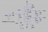
I have a single DC voltage signal that I want to feed into two separate inputs of an op amp, the op amp is to be used as a dual voltage follower.
I have attached the circuit diagram & was wondering if the circuit will be suitable but more to the point if I have actually done it correctly?

Should I have resistors in series with the op amp inputs?

Thanks
 

Attachments

  • Dual DC Voltage Follower.PNG
    Dual DC Voltage Follower.PNG
    23.8 KB · Views: 253
As long as everything is within the input common mode range and output voltage swing range, looks fine. No input resistors needed, but a short or other problem on one opamp output might influence the other opamp input. What is the TL074 notation?

ak
 
I will be using a TL074 op amp as I have two separate DC signals that I need to split into 4 outputs, just drew one side on the diagram.
Just had it there as a reminder as I haven't got a model for the TL074 op amp as yet.

EDIT :
Would it be better to use a couple of small signal diodes to isolate the inputs in case of a short in one op amp?

Thanks for the help
 
Last edited:
Why the pull-down resistors on the two outputs?

It looks like you are trying to filter PWM from an Arduino (500Hz). Wouldn't the opamp sections be better utilized if they were the low-pass-filters rather than just a voltage follower?
 
MikeML
Yes, your correct with the Arduino.
To be honest your suggestion of the op amp low pass filters is something I didn't even give thought to & obviously it is a very good suggestion?

Any suggestions or diagrams on how to achieve this correctly would be very helpful.

EDIT:
I thought the pull down resistors were required to keep the outputs loaded at all times?

Thanks
 
...To be honest your suggestion of the op amp low pass filters is something I didn't even give thought to & obviously it is a very good suggestion?
Any suggestions or diagrams on how to achieve this correctly would be very helpful.
Do you have a spec for how fast you want the opamp output to settle to a new value when you change the duty-cycle inside the Arduino? Read post #33 of this forum thread to get started with the low-pass filtering of the Arduino PWM
I thought the pull down resistors were required to keep the outputs loaded at all times?...
Nope. Opamps have a push-pull output stage, so they are as good at sourcing current as they are at sinking current.

A new question? The only reason for having two opamp followers is because one opamp cannot either source or sink enough current to drive your load(s). The output of an opamp has almost zero output impedance provided that you do not exceed the max. allowed source or sink current, so you can likely just parallel your external loads onto one opamp. What are the loads you expect the opamp(s) to drive?
 
Last edited:
Opamps work perfectly with or without a rated load. Then the pulldown resistor and output capacitor are not needed.
TL07x opamps have a limited common-mode input voltage range. They must not be within 3.5V from the negative supply voltage that is 0V in your circuit. Then the inputs do not work properly if they are less than +3.5V. Actually if an input voltage goes less than +3.5V then the output suddenly goes as high as it can. This error does not happen if the recommended dual polarity supply is used. The output also does not go anywhere near 0V in your circuit. Use opamps designed to use a single positive supply instead.
 
An output capacitive load on an op amp, such as C2 and C3 can cause oscillations.
What is their purpose, as all they would do otherwise, is just slow down the rise and fall time of the op amp?
 
Some very good replies here & things I was unaware of:

The reason I have been loading the output is due to the datasheet I have that mentions somewhere that the Outputs should be loaded & they show the pull down resistor etc as an example as you will see in the attachment.
Obviously I thought they were necessary?

MikeML.
The settling speed would be best kept to around 300-500mS or better if it can be done for step testing of some things I am learning about.
The load that the output voltage is being feed to is another Arduino Board so the I/O pins are rated at 40mA each, I hope this is what you need?

audioguru,
Thank you for the information about common mode input voltage range, I was not understanding this correctly until now.
The only opamps I have that may be suitable are LM324 or LM358, the operating voltages I need are 0v to 5V maximum..

Thanks

Edit:
crutschow,
Sorry I missed your reply.
As mentioned above that the pull down resistor & cap is suggested in the datasheet to keep the outputs loaded at all times?
Thanks
 

Attachments

  • Loading Output.PNG
    Loading Output.PNG
    37.2 KB · Views: 193
Last edited:
I have simulated the circuit in the attachment but it is a dual supply circuit & I am not sure how to do this with a single supply as required?

Thanks
 

Attachments

  • Low Pass Filter.PNG
    Low Pass Filter.PNG
    28.7 KB · Views: 126
that the pull down resistor & cap is suggested in the datasheet to keep the outputs loaded at all times?
That's not a recommendation, that's a test load to simulate normal operating conditions and stray capacitance.
Normally you never add capacitance or a load resistor to the output of an op amp other than required by the normal load.
I have simulated the circuit in the attachment but it is a dual supply circuit & I am not sure how to do this with a single supply as required?
Ground the negative supply pin of the op amp and add a DC offset to the input source equal to 1/2 the supply voltage.
 
I need a bit of help with this;
"add a DC offset to the input source equal to 1/2 the supply voltage."

Where exactly do I connect the 1/2 VCC on the circuit posted above?

Thanks
 
In some audio applications, a constant load from the output to the negative rail reduces crossover distortion. Not an issue in your application.

ak
 
Your filer is 560 ohms and 100uF.
You should get the same function from 5.6k and 10uf. (smaller capacitor)
------------------------------------
If you want the output to go (0 to 5V) you will need a R-R input/output amplifier. (rail to rail) Most amps will not work with the inputs and outputs near the supply voltage.
-------------------------------------------
The bottom amp has a frequency response in blue.
The top amp has a frequency response in green. It is faster at 10hz. We don't know what your PWM frequency is but say maybe 500 hz. At 500 the green trace has less ripple on the output. (removes more noise)
upload_2017-5-2_21-28-44.png
 
Thanks Ron,
I will have a look at that.

I have been trying to get MikeML's Circuit working in LTspice from the link he posted but I am having a switching problem or something, not sure really, attached is a screen shot of the pwm output & it switches on at 100mS & is not the same?
I understand that my pulse from V6 is set to 100mS but I do not get the same results as Mike did with the same pulse settings, I am missing something?

Thanks
 

Attachments

  • PWM.PNG
    PWM.PNG
    63 KB · Views: 125
Last edited:
I have been trying to get MikeML's Circuit working in LTspice from the link he posted but I am having a switching problem or something, not sure really, attached is a screen shot of the pwm output & it switches on at 100mS & is not the same?
I understand that my pulse from V6 is set to 100mS but I do not get the same results as Mike did with the same pulse settings, I am missing something?

Thanks
Been busy. Here is the original circuit. You likely do not need the second stage U1. That was specific to the requirements in the original thread. U2 is any rail-to-rail in-out modern OpAmp.
 

Attachments

  • Draft8p.asc
    3.7 KB · Views: 101
Last edited:
Thanks MikeML,
I decided to spend some time & learn more about filtering so I can understand all this better & have found some good reading.
I will run your simulation & have a look at it.

Thanks
 
When using filters it appears that everything is calculated for AC signals which differs for square wave or pwm signals, if so is there a constant figure or something that has to be accounted for when calculating things when using other than sine signals?

This may be overkill but using the circuit provided I have added another filter to the output which has positive effects on the output ripple etc as can be seen in the attachments, will this cause any issues that I am not understanding.
It's probably not needed but I wanted to see if I could improve things?

Thanks

Edit:
The next things is can I just split the output of the filter into two to feed two input ports of the Arduino?
Do I need series resistors etc to do this?
 

Attachments

  • Ripple.PNG
    Ripple.PNG
    37.1 KB · Views: 106
  • Filter Comparison.PNG
    Filter Comparison.PNG
    50.7 KB · Views: 106
  • Settling Time.PNG
    Settling Time.PNG
    14.7 KB · Views: 95
Last edited:
A squarewave has a sinewave fundamental frequency plus many harmonics. If you use a sharp filter to remove its harmonics then you are left with its pure fundamental sinewave.
A filter design can resonate and cause ringing, or it can be designed not to resonate with a smooth output.

PWM uses frequencies so high that it cannot be heard, seen or felt. Then a filter is not needed. Your frequencies are much too low.
 
Status
Not open for further replies.

Latest threads

New Articles From Microcontroller Tips

Back
Top