Continue to Site

Welcome to our site!

Electro Tech is an online community (with over 170,000 members) who enjoy talking about and building electronic circuits, projects and gadgets. To participate you need to register. Registration is free. Click here to register now.

  • Welcome to our site! Electro Tech is an online community (with over 170,000 members) who enjoy talking about and building electronic circuits, projects and gadgets. To participate you need to register. Registration is free. Click here to register now.

DSB-SC versus SSB-SC Demodulation, Continued

Status
Not open for further replies.
K

KerimF

Guest
About 6 years ago, I started this thread. I re-started it for the undergraduates and professors who are interested in the AM communications system.

I uploaded LTspice files. They simulate the simplest reliable analogue AM demodulator which works for all modulation indexes; from m=0 (no modulating signal) to infinity (no carrier).

Its PLL (just one loop, not two in quadrature as in Costas Loop) locks with the suppressed carrier (frequency and phase). So, it has a frequency lock range much like in FM receivers. Also, unlike the case of the Squaring Method, it doesn’t need any selective filter, passive or active.

As you will see, its circuit could be integrated in a relatively low-cost IC (for MW and SW bands, in the least). But since all IC manufacturers and the universities around the world have no idea of it, the DSB-SC system lost its importance with time. It happens that the two well-known topologies for a DSB-SC demodulator are not practical for the general use (you may like to see the actual FCC regulation about using DSB-SC system).


The disadvantage of DSB-SC system is that its channel bandwidth is twice of the SSB one. But, on the other hand, its modulator is simpler than of a SSB-SC one (mainly about filters). And, it has the best power efficiency, no voice gives no RF output. In fact, this second feature lets it likely be the best choice for the aviation RF communications near the crowded airports. It minimizes automatically the interferences which could be produced by several transmitters working on the same channel in the same period of time; for example, a pilot just needs to stop talking to turn off its RF signal completely and automatically while listening to someone else talking on the same channel.


Anyway, I guess it is too late now for the world to go back and take advantage of the DSB-SC system. I mean; the innovative topology of the versatile AM demodulator (carrier suppressed or not) here became just a new academic idea, now. It just proves that “demodulating a DSB-SC signal is much easier and more reliable than demodulating a SSB-SC one (mainly for radio amateurs). In other words, it proves the inverse of what it is believed and taught in all universities actually.

Based on the human logic, I believed, before I started my MS thesis in year 1979, that getting more coherent data (as the two symmetrical sidebands in DSB-SC) has to make life easier than getting less data (as the one sideband only in SSB-SC).


Cheers
Kerim


Please note:

[1] On my laptop, the various LTspice traces start to show up about 75 sec (100us real time) after running the simulation. For this reason and to those who don’t have LTspice, I also included 4 images in the attached zip file.

[2] The demodulator which I used in my private short-range RF links (in the 80’s), didn’t have the blocks X2, X4 and U2 (on the actual schematic). And it worked fine for several years.

[3] After installing the LTspice simulator, I had the idea to make it better in case an IC manufacturer may like its topology to patent it and produce a new family of ICs (likely for SW radio amateurs who can get a license in using the DSB-SC system).
 

Attachments

  • DSB-SC_455K_PLL.zip
    392.5 KB · Views: 169
I thought I will get some comments, if not professional remarks, negative or positive.
For instance, I forgot that I was registered here as Kerim many years ago. I mean, Kerim and KerimF are one here :)
 
I thought I will get some comments, if not professional remarks, negative or positive.
For instance, I forgot that I was registered here as Kerim many years ago. I mean, Kerim and KerimF are one here :)
Split personality here, eh? :cool:
 
Split personality here, eh? :cool:
Actually, it is short of memory :(

I forgot that only since about 5 years ago (that is soon after I joined here, the first time) I started using KerimF as my username. So, when I registered with KerimF and with an email address different from the first one, there was no complain about both.

I think, thanks to your remark, I need to cancel the new one and then change the first username from 'Kerim' to 'KerimF'. Doesn't this work?
 
It minimizes automatically the interferences which could be produced by several transmitters working on the same channel in the same period of time;
How does it handle the situation of several transmitters all at slightly different SC frequencies? AM sort of handles that as long as the heterodynes don't get into the AF band, though you get fading. But your PLL can only sync to one. Trying to demod a DSB sig with an unsynchronised carrier doesn't work well, the aircraft carriers aren't going to be synchronised, and doppler would screw things up even if the carriers were on TX.
 
How does it handle the situation of several transmitters all at slightly different SC frequencies? AM sort of handles that as long as the heterodynes don't get into the AF band, though you get fading. But your PLL can only sync to one. Trying to demod a DSB sig with an unsynchronised carrier doesn't work well, the aircraft carriers aren't going to be synchronised, and doppler would screw things up even if the carriers were on TX.

Good remarks, thank you.

First, if many nearby speakers transmit on the same frequency, naturally all have to be quiet but one, at a time. And this one will likely end his message by saying something like 'to X, over' so that X can talk and so on. It is as simple as this.

Second, the suppressed carriers don't need to have the same/exact frequency as long their frequencies are in the capture range, better in the lock range which is also wide enough to be practical.
By the way, to scramble my first private short-range RF voice link on the AM band (in the 80s, Aleppo city), I took advantage of my DSB-SC demodulator by varying the frequency of the suppressed carrier sinusoidally about +/- 30 Khz and at a rate of about 6 Hz. The conventional AM band receivers, at that time, detected, while transmitting, just a wide noise-like interference covering a few AM channels while my receiver recovered the transmitted voice normally. But soon later, I preferred working on the FM band. The voice signal was transmitted on 32768 Hz instead of the suppressed 38 Khz used in stereo FM (for L-R). Naturally, I didn't need to add a pilot (as the 19 Khz). and I kept the baseband (L+R) empty, so that an FM radio set could just detect a silent channel.

I hope this answered your remarks.

Kerim
 
Last edited:
Your sim doesn't run in my version of LTS., missing 4013B and LM339. Anyway - from the PNG schematic at a guess it works thusly:

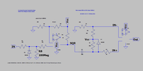
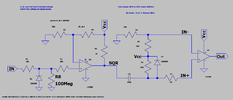
AIUI, You generate 0.25 cycle width pulses from both positive and negative crossings of the IF in elements X1 and X2, sum the o.c. outputs pulled up by R4 to get a sort of 50% squarewave at 2IF, which is synchronised with the zero crossings, maybe a little bit delayed. The PLL VCO presumably runs at 2IF and the o/p of the XOR phase comp is passed to the PLL vontrol voltage LP filter, pre filter R8/C& to take the edges of and main filter R1and C2 with a zero added in with R3. The error signal is gated out before the filter when there's insufficient IF signal.

So you have a VCO signal in some fixed phase relationship with 2IF, gated out at modulation zero crossings and it's divided by 2 in U3 and synchronously rectifies the IF signal.

Which seems fair enough for strong signals, and maybe the PLL smooths noise enough. I tried listening to an AM station on 909kHz with a SDRplay RSP1A as AM and then synchronous AM DSB, then reducing the RF gain. I was surprised that the S-AM DSB performed well, perhaps better than AM as gain dropped and noise increased. I tried pure DSB demodulation and got fading, presumably as the unsynced injected carrier slowly rotated relative to incoming the sidebands. Which is the typical objection to decoding DSBSC without filtering one sideband out.

Questions would still remain as to what happens as the AGC boosts gain on noise (which could impair the gating function) but yes, it is probably a decent way of demodulating a DSBSC and a AM signal.

In a SSB net listeners can still hear what's going on even if two people double, though of course the doubling speakers can't. Not sure how that would work with this and DSBSC

However, the advent of DSP has probably wiped out the opportunity for a novel analogue approach to demodulating DSBSC. So a pleasant intellectual exercise, and it probably would work, but the ship has sailed I think. But a nice idea
 
ermine,
In the 80s, I lived in a rather poor neighborhood, so I had no phone line. My apartment was about 3 km far from my workplace located in the city center. As I mentioned earlier, my first two voice links (two directions), between home and workplace, were on MW band with the suppressed carrier oscillating at a rate of 6 Hz covering about 6 channels. It worked well for about one year before I had the idea to use the FM band instead (also as explained earlier) for a few years till I got a phone line at home. (Later, I moved near the city center).

I mean, as far as I know, this simple-to-build demodulator helped me have my 'private' voice links when I was in need. The received voice was clear always as if we talked on a bell phone. But perhaps this was possible in my environment only which was perhaps relatively clean from interference, at that time, on MW and FM bands. I wonder if it performs well on the SW bands. I couldn't test it because this needs two radio amateurs who also live far from each other.

Very soon, I will attach the models 4013B and LM339.
 
ermine,

CD4013B is already in CD4000.lib (also included in the attached zip file).
I attached LM339.zip.
 

Attachments

  • LM339.zip
    1.4 KB · Views: 149
Sorry, it seems the asy of CD4013B is missing; attached here.
 

Attachments

  • CD4013B.asy
    1,018 bytes · Views: 151
Thanks, this now compiles. I have not played with .tran in LTspice although i have done it in other spice versions. It is news to me that you can do a transient sim of a 4046 PLL at all, so I will have learned something new and useful if that is the case ;)

However there is still an error I had to mod your X1 because I think your LM339 model has changed. What I had originally was

x1-ori.png and I edited it for x1.png

I was not sure if I should switch + and -, but for now it seems to give a trace on dsout
vdsb-audio.png

What I can't get is a useful demod. I switched from the gaussian noise to the sinewave because it's the devil's own job to tell the original noise signal from the demod o/p where the unlocked carrier is rolling through. It is much more obvious on the sinewave baseband signal to me.

Although demod is fine without the control loop working (I don't know where Vmute should be) that's only if you set F_mid to 910k, in a simulation that will be exactly the right frequency of course. I tried setting it to F_mid = 911k just to give it a little bit of offset which should easily be within the capture range of the PLL, and the input signal to sine,

vout_scroll.png

and the signal recovery isn't right. But perhaps I have butchered your simulation trying to correct the LM339 error. If I set the VCO back to your 910k then it is all dandy, but the VCO has no work to do in the ideal world of simulation
vout_nscroll.png

so I am not so sure how it would work IRL from the simulation
 
Thank you for sharing your tests. As soon as possible, I will have a look at what you have pointed out here. Unfortunately, in these days, I am busy more than usual.

To my knowledge, changing F_mid or 455 Khz (IF) is not supposed to distort the audio output.
For instance, I am sure that the F_mid in my real demodulators, I made in the 80's (which didn't include X2, X4 and U2), couldn't be made exactly 455 Khz and 32768 Hz respectively, due to the resistors and capacitors tolerances. But they worked very well as expected.
 
ermine

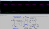
Yes, I even tested for 500 Hz sinewave, the audio output was 1000 Hz instead (see below)

DSB-SC_455K_500Hz_911Khz_1.png


The crucial block in this demodulator is the duty shaper.
So I designed another one because I didn’t like the look of V(vco_in) trace. It is supposed to be cleaner.
Please find the attached “DutyShaperIF2.asc” to replace the older one, “DutyShaperIF.asc”. Then, on the working folder:

[1] Copy “DSB-SC_455K_PLL-12.asc” and “DSB-SC_455K_PLL-12.plt” and give them another common name.

[2] Copy “DutyShaperIF.asy” and renamed it as “DutyShaperIF2.asy” to complement the new “DutyShaperIF2.asc”.

[3] On the main schematic, X1 and X2 (they were of “DutyShaperIF.asy”) should be deleted and replaced with “DutyShaperIF2.asy”.

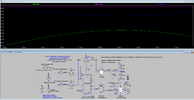
I re-run the simulation of the new schematic, it gave the same result but with a clean stable feedback, V(vco_in).

DSB-SC_455K_500Hz_911Khz_2.png


So, I guess more revisions of the schematic are needed (mainly the model of CD4046) since there is no clear reason why a difference of about 1/1000 lets the demodulator become a frequency doubler!
 

Attachments

  • DutyShaperIF2.asc
    1.6 KB · Views: 162
Last edited:
ermine

Thanks to you, I discovered that the schematic I did, to simulate the real working demodulator, has bugs (including the second proposed schematic).

On my side, I will try to find these bugs in my free time because I am sure they exist. Its topology does work in real. If someone will also have the chance to apply its topology, as I did long ago, he will realize its importance for the DSB-SC system (actually it can also demodulate any DSB AM signal).

I feel real sorry for not being aware of the hidden bugs before restarting this topic because the simulation worked fine at F_mid :(

Kerim
 
If someone worked in the PLL field, he would know already that the crucial part in this demodulator is the low pass filter (LPF) of its loop phase error (between PC1 and VCO_in).

I noticed now that the RC LPF, which I did for simulation about 12 years ago, is totally wrong!

Sorry, for any inconvenience.


The actual PLL settling time which I was able to achieve now, is about 120us (the new schematic is attached here, DSB-SC_455K_PLL-v2.zip).

DSB-SC_455K_PLL-v2_p.png


Therefore, the audio output in the first 100us depends on the initial conditions (after a silence, no RF signal) of the capacitors at the audio output and LPF.

Who knows... perhaps someone will have time to make its performance even better.

Have fun.

Cheers,
Kerim
 

Attachments

  • DSB-SC_455K_PLL-v2.zip
    348.1 KB · Views: 146
In 1979, I couldn't submit my work (the basic version of this demodulator as an MS thesis). I had to return home for financial reason before doing it (besides the instability in Lebanon during the following years).

My first attempt to demodulate a DSB-SC signal (at the university lab) was to demodulate it first by a full-wave rectifier. And, at every zero crossing, the rectifier output is reversed in polarity to recover the original AC audio signal. Unfortunately, it worked for voice/speech signal not of music. After all, the envelop of a complex audio signal may be close to zero once a while without crossing it and this generates false zero crossings. But this drawback didn't prevent this method being patented by 'Charles B. Fisher' a few years later, (United States Patent 4430620, Demodulator system for double sideband suppressed carrier amplitude modulation).

After rejecting the reversal method and during about 3 months, many designs failed, mainly for being not practical, till I had 3 days only before leaving the lab for good. During my failures, I didn't try using the PLL topology for two reasons; it is used in Costas Loop already and, in theory, a conventional loop is not supposed to lock while the phase of the carrier reverses at every zero crossing. I am not sure how I had the idea of using PLL whose Fo (F_mid) is twice the carrier frequency. I did it though I was sure it couldn't work. To my big surprise, it worked! I thought first that I connected, by mistake, the input signal to the output. But when I varied the carrier frequency the output signal was lost. I also noticed a small lock range! Truth be told, I had no idea, at that moment, how this was possible to happen. And I had no more time to analyze the circuit at lab and returned home. At home, I rebuilt it and watched the signal at every node on my first humble oscilloscope. I found this:
Between the DSB-SC input signal and CD4046, there was an LM339 comparator (used as a high gain amplifier, a limiter). The duty cycle of its output was supposed to be 50%. But since it is not ideal, its different internal delays for the rise and fall edges, let the duty cycle be also different, about 49%. This very small difference was enough to produce a stable phase error in both polarities. A further study shows that a duty cycle of 25% (or 75%) gives the widest lock range.

Have a nice day,
Kerim
 
For instance, I don't expect to have any credit for this innovative simple demodulator which is still assumed not existent, as it was the case in 1979 when I worked on it.

Sooner or later, I will die, being an old man now. So, I posted it here to avoid its death with me.

I just wish, if possible, to hear when someone find a way to make its topology useful to him; by presenting it as a thesis or to get a patent, if not by applying it in a real experimental RF link.

Best wishes to all,
Kerim
 
Status
Not open for further replies.

Latest threads

New Articles From Microcontroller Tips

Back
Top