oliverb
Member
I am building a new slave clock for my master clock (see under projects mater clock woth 7 segment dislay).
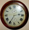
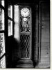
I have an old 12" dial clock case and plan to use a 30 sec clock motor for the hours and mins and 2 modified quartz clock motors for the seconds and date displays. I have enclosed a mock up picture of how the clock should look.
I have built a driver for the quartz clock motors using a 2 sec pulse from my master and a 4093 chip I had spare.
The cct works fine and has driven the quartz clock motor perfectly over the last couple of days.
I am not sure how to protect the 4093 chip from back emf from the motor coils. I would normally use reverse diodes across the motors but as the cct reverses polarity to the motors every second I don't think ths will work.
Any ideas?
Thanks.
Brett.
Attachments
Last edited:
 .Are you saying triggered for a 2 sec period or 1 pulse every 2 secs?