Continue to Site

Welcome to our site!

Electro Tech is an online community (with over 170,000 members) who enjoy talking about and building electronic circuits, projects and gadgets. To participate you need to register. Registration is free. Click here to register now.

  • Welcome to our site! Electro Tech is an online community (with over 170,000 members) who enjoy talking about and building electronic circuits, projects and gadgets. To participate you need to register. Registration is free. Click here to register now.

Driving an LED Display circuit help

Status
Not open for further replies.

GrimmthaKingpyn

New Member
Hi,

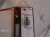
I'm having trouble building a circuit to Drive a seven segment LED to cycle thru all 10 digits. Below is the schematic that I followed and the next pic (albeit a little fuzzy) is the breadboard prototype. Is there any way you guys could tell me (if you can actually see any detail) if I wired it up right or not.

circuit scheme.jpg

DCFC0001.JPG

DCFC0005.JPG

First time I built it I grounded all of the pins that weren't used. When I flipped the SPDT switch to the on position my voltage dropped from the 3V supplied to .9V and my current went high. When I removed the wiring grounded pins it doesn't react at all.

I programmed my PIC16F684 with the code I wrote in C language. and used a DC power supply instead of batteries.

I appreciate all helpful comments!!

GrimmThaKingpyn
 
You need current limiting resistors on the segments. 330 ohm is a good choice.

Those Evil Genius books are OK to complete crap. That one looks the the Myke Predko book, usually his stuff is good.
 
Guys i think using pic for counter is like killing a fly with a bazuka. why dont u use 7 segment display? at list you dont need a prophet to tell u if the circuit is wrong or not. if im not mistaking
 
Guys i think using pic for counter is like killing a fly with a bazuka.
Maybe he wants to learn how to program and wire up PICs, and simple projects like this are a good way to do so. ;)

Anyway, first of all you'll need current limiting resistors on the segments, to protect both the LEDs and the PIC.

Next, post your code. No display could be a problem with the circuit wiring or a problem in the code. You did flash your code into the PIC, right?

Do you have info on the 7-segment display? Datasheet? Pinout?
 
Maybe he wants to learn how to program and wire up PICs, and simple projects like this are a good way to do so. ;)

I agree! I used a ~£145 development kit (microprocessor and a prototyping board) to make a working pedestrian crossing using green, yellow, and red LEDs, and one of the onboard microswitches :D
 
Thanks for all of the feedback! Yeah I did flash the code into the PIC it is as followed:

#include <pic.h>
/* c7Segment.c - Roll through 10 Digits on 7
Segment LED Display

This program will display each of the Decimal
10 digits on a 7 Segment Common Cathode LED
Display.

Hardware Notes:

RA5 - Segment a
RC5 - Segment b
RC4 - Segment c
RC3 - Segment d
RC2 - Segment e
RC1 - Segment f
RC0 - Segment g

Ken J.
9.14.08

*/

__CONFIG(INTIO & WDTDIS & PWRTEN & MCLRDIS &
UNPROTECT & BORDIS & IESODIS & FCMDIS);

int i, j, k;

const char LEDDigit[10] = {
// RRRRRRR - PIC16F684 Pin
// ACCCCCC
// 5543210
// abcdefg - LED Segments
0b1111110, // Digit Zero
0b0110000, // Digit One
0b1101101, // Digit Two
0b1111001, // Digit Three
0b0110011, // Digit Four
0b1011011, // Digit Five
0b1011111, // Digit Six
0b1110000, // Digit Seven
0b1111111, // Digit Eight
0b1111011}; // Digit Nine

main()
{
PORTA = 0;
PORTC = 0;
CMCON0 = 7; // Turn off Comparators
ANSEL = 0; // Turn off ADC
TRISA = 0b011111; // RA5 is an Output
TRISC = 0b000000; // All Bits of PORTC are Outputs

k = 0; // Start at Digit 0

while(1 == 1) // Loop Forever
{
for (i = 0; i < 255; i++) // Simple Delay Loop
for (j = 0; j < 129; j++);

RA5 = LEDDigit[k] >> 6; //Pass Data Bits to LED Bits
PORTC = LEDDigit[k] & 0x03F;

k = (k + 1) % 10; // Increment k within range of 0-9

} // elihw
} // End c7Segment


It succeeded when I built it. And flashed correctly with the checksum being verified. Let me know if my program looks bad!!!!

I've attached the datasheet below:

View attachment 7 segment datasheet.pdf

Thanks again guys!!! I'm gonna rewire it and retry!!
 
Haven't looked in detail at your code, but typically the breadboard you are using needs some extra jumpers which I've added in red. They are also needed on the left side of the picture also, but the image made this difficult to show.
 

Attachments

  • DCFC0005.JPG
    DCFC0005.JPG
    232.7 KB · Views: 653
thanks for the pic idea. actually, i cant program im trying to learn with c. what i realy meant to say at the first time was the use of 4026 and 555 to drive the 7 segment. you ve done it with pic. i would love to learn from you how about that?
 
Status
Not open for further replies.

Latest threads

New Articles From Microcontroller Tips

Back
Top