Hi
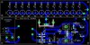
I've built **broken link removed** circuit for LED emergency light which turns the LEDs on when there is power failure.
It use BD140 pnp transistor for this purpose. I have 60 LEDs in the panel which are best operated at 3.25 volts drawing 950 mili amps.
BD140 only gives 3V and max current of 450 milli amps (without any resistance attached to LEDs) so the LEDs don't glow as bright as they should.
I tried BD176 but the results were worse then before i could only deliver 250 miliamps (without any resistance)
I then trided TIP42c, it gave 650 mili amps @ 2.98 volts without applying any reistance.
What would be the best transistor in the circumstances which could deliver the desired voltage and current.
PS: My knowledge in electronics is just basic.
Thanks in advance
Waseem
") it worked very well
it worked very well