Continue to Site

Welcome to our site!

Electro Tech is an online community (with over 170,000 members) who enjoy talking about and building electronic circuits, projects and gadgets. To participate you need to register. Registration is free. Click here to register now.

  • Welcome to our site! Electro Tech is an online community (with over 170,000 members) who enjoy talking about and building electronic circuits, projects and gadgets. To participate you need to register. Registration is free. Click here to register now.

Drawing Waveforms or how to draw waveforms

Status
Not open for further replies.
walters said:
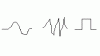
capacitors and timers etc. to draw fancy waveforms

So timers circuits can take a input signal and output different slopes,curves,shapes of different waveforms?

Not exactly, what i meant was there are a lot of circuits using different devices, sometimes 555 timers, sometimes flip-flops, etc. and almost always some capacitor/resistor circuitry to create waveforms, clock pulses, etc. I suggest you google some keywords like wavefrom+circuit or something and you'll get some simple circuit outlines. The frequency of the waveform will usually be determined by the RC time constant of the capacitor resistor combination. As I aluded to earlier, a large value capacitor and a high resistance resistor will produce a very slow charge discharge and thus a very low frequency waveform that can be plotted on a chart recorder. Very simple stuff that will impress your teacher if you take the time to do it right. You could draw a very pretty picture of ocean waves with a simple capacitor/resistor series combination.

EDIT...I forgot to add that there has to be a switching device like a transistor in the circuit to control the charge and discharge of the capacitor. A simple do it yourself circuit could even use a manual switch to do the trick, but the best way to do it would be to have a clock pulse circuit gate the transistor on and off.
 
Thanks alot guys

So a arbitary function generator will output more complex waveforms than just sine,triangle,square?

Does arbitary function generator outputs different curves,shapes?
 
pretty picture of ocean waves with a simple capacitor/resistor series combination.

How would it be looking like ocean waves from just one network of capacitor/resistor?

Ocean wave network:
capacitor/resistor discharging output#1
capacitor/resistor discharging output#2
capacitor/resistor discharging output#3
" in parallel/series network i could see
with 3 different discharging outputs?"
 
A simple circuit with one capacitor in series with one resistor will give a waveform that looks like ocean waves. Here is a simple example of one of these circuits
**broken link removed**

The switch could be a transistor driven by a pulse generator.

Very elemantary

Build some circuits like this and measure the output with a chart recorder.
 
how is the math too complicated?

say you want to plot a sine wave of a certain magnitude and frequency, you just use A*sin(freq*t)...where A is the amplitude and freq is the freqency...
 
https://www.tti-test.com/products-tti/generator/wavemanplus-screen.htm

https://www.tti-test.com/products-tti/generator/wavemanplus.htm


PC waveform editing software?

ArbExpress™ Software for Arbitrary and Function Generators

Math Operations on Waveforms (from Waveform library, Scalar & Clip Board)

ArbExpress™ gives you the freedom to create standard functions in addition to complex "arbitrary" signals - signals with noise, glitches or arithmetically derived properties.

Interactive waveform editor to design custom signals to fit the needs of your application

The new AFG3000 series offer function, arbitrary waveform and pulse generators with unmatched performance, versatility and affordability. A large display shows all relevant waveform parameters and graphical waveshape at a single glance.
ArbExpress software is included which allows waveforms to be downloaded directly from selected Tektronix oscilloscopes via or created with the equation editor and waveform maths

DC waveforms

IntuiLink Waveform Editor V1.4 for 33120A, 33220A, 33250A Function / Arbitrary Waveform Generator

IntuiLink Waveform Generator is powerful stand-alone application for creating arbitrary waveforms. Waveform data can be imported from a file, or captured using a supported Agilent oscilloscope. Waveforms can be modified or designed from scratch using the powerful waveform editor. Once the waveform is created it can be downloaded to the function generator. In addition, complete instrument setups can saved and restored from the PC.

Create waveforms graphically
 
These looks like it:

Wavesmith™ Analog Waveform Development System

**broken link removed**

https://www.wavebuilder.com/

**broken link removed**

WaveCAD is a powerful Windows-based design
WaveWorks Pro+ - Advanced Waveform Creation Software for all TEGAM AWGs
WaveWorks Pro+™ turns your computer screen into a waveform palette. With its extensive waveform library and complete set of design and editing tools, WaveWorks Pro+™ provides unlimited waveforms and waveform sequences when coupled with TEGAM's arbitrary waveform generators.
 
walters said:
But then thats just one ocean wave?

I thought u ment like multiple ocean waves discharging

I did mean multiple waves. That is what the switch creates when OSCILLATED back and forth. In the simple mechanical switch, the human would watch the waveform being drawn on the scope or recorder, he would see the rise to peak of the waveform, he would then move the switch to allow the discharge, the waveform would crest and quickly fall back to zero in exactly the same period as it took to charge. Again the human would move the switch and the charging cycle would occur again. This process can be repeated as many times as you like creating multiple waveforms. The eyes and hands of the human create the "feedback loop" that generates the oscillation. However, in a more complicated and practical waveform generating circuit, there is a more automated circuit to create a feedback loop, that will "toggle" a transistor or multiple transistors instead of manual switches.
 
walters, in reality there is only two types of waveforms, and that can be streatched to 3

DC
Sinusoid
Exponential

With those three you can make any kind of waveforms
 
I'm no Picasso, but this aint too bad for hand drawn waveforms.
:lol:
 

Attachments

  • wf.gif
    wf.gif
    645 bytes · Views: 730
I generated these images in under 10 minutes using MATLAB.

They are:

2 cycles of a cosine
AM Modulation
16-ary QAM
 

Attachments

  • qam.jpg
    qam.jpg
    34 KB · Views: 711
  • cos.jpg
    cos.jpg
    18.6 KB · Views: 705
  • am.jpg
    am.jpg
    44.4 KB · Views: 707
Those MATLAB graphs are pretty slick, _3iMaJ. Do you know of any good M file tutorials for us to check out?
 
_3iMaJ, increase yr sample density the 3rd starting to look jaggedy
 
_3iMaJ said:
Styx,

On the 3rd graph that wasn't possible it would violate the Nyquist rate. :wink:

ahh fair enough, mmm might play aroun dwith Octave tomorrow to see wot funky plots i can make
 
I should change my name to 'chameleon' because my last question was invisible.
 
DigiTan said:
I should change my name to 'chameleon' because my last question was invisible.

Sorry about that Digitan I had to run and I couldn't write a whole lot. Yes, I have tons of MATLAB code you can look through; DSP, Communications, MIMO, Cryptography, Error Control Coding... Pick your poison my friend! :wink:
 
This is a good little script:

Code:
x = -4*pi:2*pi/200:4*pi;

%For a square wave
A = zeros(1,size(x,2));
for i = 1:2:199
    A = A + sin(i*x)/i;
end
plot(A)


%For a triangle wave
A = zeros(1,size(x,2));

for i = 0:199
    j=2*i+1;
    A = A + ((-1)^i)*sin(j*x)/(j^2);
end
plot(A)


%for a saw-tooth
plot(x-floor(x))


%for a sinc function
plot(sin(x)./x)

it highlights fourier theorum very nicely and how good maths is really needed to understand waveforms
 

Attachments

  • untitled_199.png
    untitled_199.png
    6.7 KB · Views: 636
  • untitled1.png
    untitled1.png
    7 KB · Views: 649
  • untitled2.png
    untitled2.png
    6.6 KB · Views: 652
This code will down convert a QAM modulated signal shown in the third plot by filtering the data shown in the 2nd plot. The 1st plot is the result of the filter.

Code:
% This function will down convert a waveform to baseband.  That was
% modulated using QAM IE mod_data = a(t)*cos(2*pi*fc) - b(t)*sin(2*pi*fc)
% % The factor of 2 that appears in the trig identity is accounted for
% IE (cos(a))^2 = 1/2 + cos(2*a)/2
function [demod_I, demod_Q] = down_conv(data, Ts, fc, filter_coeffs)

n = 0:length(data)-1;
in_phase = cos(2*pi*fc*n*Ts);
quad_phase = sin(2*pi*fc*n*Ts);

demod_I = 2*in_phase.*data';
demod_Q = -2*quad_phase.*data'; % minus sign due to how the mod_data is defined

demod_I = conv(filter_coeffs, demod_I);
demod_Q = conv(filter_coeffs, demod_Q);
 

Attachments

  • qam_286.jpg
    qam_286.jpg
    36.7 KB · Views: 644
  • filt_762.jpg
    filt_762.jpg
    23.4 KB · Views: 627
  • demod.jpg
    demod.jpg
    29.7 KB · Views: 642
Status
Not open for further replies.

New Articles From Microcontroller Tips

Back
Top