earckens
Active Member
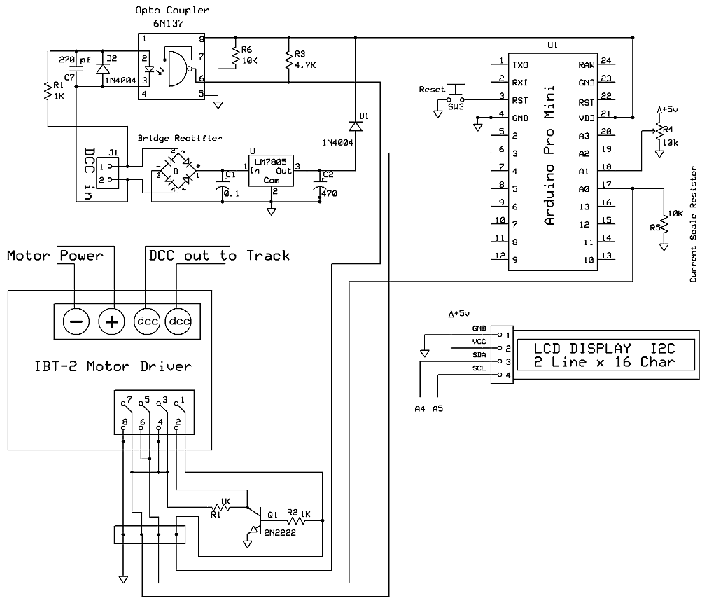
Given:
1. A BTS7960 half H-bridge mounted in a pair on a module (IBT-2) to form a full H-bridge.
2. a controller to detect overcurrent (Pro Mini, input on A0) to shut the bridge by setting output on DIO3.
3. a DCC signal that is fed straight into pin 1 (R_PWM) and inversed into pin 2 (L_PWM).
4. the Pro Mini controller will be programmed with an extra output pin that will be used to control either feed the signal as it is now into the IBT, or enables the inversing of this signal: inversed into pin 2 of the IBT ,and straight into pin 1 of the IBT.
Pinout on the IBT:
pin 1: RPWM
pin 2: LPWM
pin 3: R_EN
pin 4: L_EN
pin 5: R_IS (right current sense)
pin 6: L_IS
pin 7: Vcc
pin 8: GND
Question:
I want to get rid of this transistor and use instead a 74LS04 hex inverter and a 74LS86 quad XOR gate for this action. How do they need to be wired to allow this "reversing" or "straight" functionality, given just one output from the controller?
Background: this schematic needs to be adapted for 3 more independent IBT's, hence each of this logic IC's will be fully used.
I realise too that 3 more current sense inputs will need to go to the Pro Mini.
