Continue to Site

Welcome to our site!

Electro Tech is an online community (with over 170,000 members) who enjoy talking about and building electronic circuits, projects and gadgets. To participate you need to register. Registration is free. Click here to register now.

  • Welcome to our site! Electro Tech is an online community (with over 170,000 members) who enjoy talking about and building electronic circuits, projects and gadgets. To participate you need to register. Registration is free. Click here to register now.

Door Counter - 74LS90, 74LS47, 7-segment display

Status
Not open for further replies.

Allacra

New Member
Hello everyone :) I am making my first electronics project. (attached below)
Here are the components:
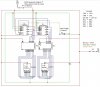
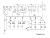
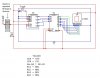
74LS90 counter
74LS47 BCD to 7-segment decoder/driver
7-segment display
Toggle switch (reset)
IR emitter and collector/detector

The switch represents the doorway. When the swith is closed, no one is in the doorway. When the switch is open, someone is walking through the doorway (blocking the voltage). I want the counter(s) to recognize the change in Voltage (when the switch goes from open to closed), it should count. The switch will begin in the closed position. The way I have it set up, it is NOT working :-(
In reality, I will have an infrared emitter and collector. When someone blocks the IR light and the collector does not detect it, then the person moves and IR light is detected again, I want it to count.
The toggle button is supposed to allow me to reset once the display reaches 99 (its maximum). It does not matter what I do to the toggle, as long as the voltage switch is closed, the counter counts. As it is, the display is only reaching 08 and is automatically resetting itself (a 0 - 8 loop).
Can anyone help me??

Thank you!

Sharon
 

Attachments

  • door_counter_project_05s.jpg
    door_counter_project_05s.jpg
    92.5 KB · Views: 5,661
I can see at least 2 issues:-

1. There are no bypass capacitors across the ICs. You need a 100 nF ceramic cap across the Vcc and gnd pins of at least every second IC. Otherwise, strange results will occur due to unwanted coupling via the supply line.

2. There is no "pull down" resistor on the S3 switch input.

This is required to ensure that the input goes from High to Low when the switch is opened.

Also there is no bounce suppression, so the counter will advance several times whenever S3 is opened or closed. This won't occur with the IR circuit, but it may count more than once when people walk through if their arms are swinging.

I would use CMOS ICs as they have much better noise immunity than TTL and the 400 series can operate with a wide range of supply voltage.

The posted circuit is simple bounce suppressor. It uses CMOS, but would work with your TTL.

I also added a counter design. Note the bypass capacitor C2.

Len
 

Attachments

  • bounce_suppressor_162.gif
    bounce_suppressor_162.gif
    2.7 KB · Views: 2,308
  • digital_dice_2.png
    digital_dice_2.png
    4.5 KB · Views: 5,196
One thing that immediately stands out to me is your counting pulse input voltage. 10vdc is too high for 74LS series chips to handle. My Signetics data book indicates an absolute maximum of 7vdc as a supply voltage or input level. Personally, I wouldn't run them much over the standard 5vdc. Stressing the chips that hard may shorten their life considerably.

** Edit ** After a closer look, your counter U2 has +5vdc connected to CP1 input and by connection to Q3 output of U1. In addition, CP0 and CP1 inputs on U1 are connected together. Your circuit certainly won't work too well with those connections. For divide-by-ten (normal counting) mode on a 74xx90 counter, pins 2, 3, 6 and 7 should all be at ground (ignoring for now the fact that you desire to reset the counter at random) and pins 11 and 14 should be connected. Your clock (count) pulse should go into pin 1.
JB
 
Thank you to the two have answered already...I'm still having problems though :-( Now I have it to where it will count to ONE haha...01...Maybe I'll have to teach it to count? :-D
It seems like many electronics students are posting now...end of the semester.
If anyone else has ideas about this project, feel free to post! :-(


Too many wires...spaghetti

Sharon
 
Sharon,
It is difficult to make any further comment without seeing your circuit.

Len
 
Here is the circuit with only one of each component to simplify, and I have changed the positions of some.
I added in a little grey box representing a doorway. The counter should detect when the circuit is broken by a person walking through the door and should count each time. It should count to 9. Then I should be able to reset with the toggle.

The datasheet said to connect Qa (Q0 in diagram) to CKb (CP1) for BCD count...I did that.

Red is High, Blue is Low, Green is Z??? niether high nor low?
I constructed the circuit using Circuit Maker Student.

Thanks,

Sharon
 

Attachments

  • new_door_counter__one_display_.jpg
    new_door_counter__one_display_.jpg
    48.6 KB · Views: 6,539
Firstly, There is no "pull down" resistor on CP0. Thus there is no change of potential when the switch goes open. So the counter only sees one clock pulse. I suggest you insert a 4.7k resistor from CP0 to gnd.

Remember that CMOS devices have very high input resistance so their inputs need to be forced either high or low by the external circuitry.

Secondly, I don't see any bypass capacitors - as I mentioned before. Without these, you are likely see strange results.

Also contact bounce will make the counter increment many times each time the switch opens or closes.

Len
 
Allacra said:
Red is High, Blue is Low, Green is Z??? niether high nor low?
The 74LS47 IC has open-collector outputs for the segments. For the number 0 in the 7-segment display format, the transistor which drives the "G" segment is turned off, ie. not conducting, so it shows up in the sim as Hi-Z.

I think the circuit would work if you built it, but you should also put a current limiting resistor in each of the lines between your decoder outputs and your led connections. Otherwise, your display may not last too long from passing too much current thru the segments. Common values for this would be 220 or 330 ohms, depending on how bright you want the display.

JB
 
How about using my Up/Down counter.

**broken link removed**

Probably Simpler that your design.
 
I have a problem with your last counter circuit you show on here.

#1, like the other guy says, you need a pull down resistor. Connect C0 to one end of a 1K resistor and connect the other end of the 1K resistor to ground. I think that most IC's take floating inputs (inputs not connected to anything) as positive inputs. When we use a pull down resistor, we are making the IC assume that a negative voltage is received by default. The only way to change that is to apply a positive voltage directly to the pin.

#2. I don't understand why C1 is connected to Q0. If both C0 and C1 require an edge triggered input, then your counter is going nowhere.
Try connecting C1 to C0.

C1 and C0 are the clock inputs, or maybe they are cp1 and cp0. I can't see images when replying :(
 
mstechca said:
I don't understand why C1 is connected to Q0.
The input clock for the divide-by-2 counter is CP0 and the only output of that counter is Q0. It (Q0) provides a clock pulse (actually a high-to-low edge signal) to the input of the divide-by-5 counter.

mstechca said:
Try connecting C1 to C0
If CP0 and CP1 are connected together, the count sequence won't be what you'd expect. It would go something like: 0,3,4,7,8,9 etc. I think the latest diagram would work, except for the pull-down and the led current limiter resistors.
JB
 
Update on project - almost a year later!

Well...just to let whoever reads this know...
I never got the stinking thing to work. I got the first digital display to work, but that's it. It never did count right. I did okay on the assignment though...it didn't have to actually work...I just had to have an idea about the design and components to use.

Thanks for everyone's assistance!

Sharon
 
Hi Sharon.
Check the MODE SELECTION chart on the datasheet for the 'ls90... You'll find that your master resets should not be driven high when used as a counter. Otherwise your counter should work well with a digital (eg, infrared) signal.
Hook MS1 (pin 6) and MR1 (pin 3) to ground, your count signal to CP0 (pin 14), and CP1 (pin 1) to Q0 (pin 12)
 
Status
Not open for further replies.

Latest threads

New Articles From Microcontroller Tips

Back
Top