Continue to Site

Welcome to our site!

Electro Tech is an online community (with over 170,000 members) who enjoy talking about and building electronic circuits, projects and gadgets. To participate you need to register. Registration is free. Click here to register now.

  • Welcome to our site! Electro Tech is an online community (with over 170,000 members) who enjoy talking about and building electronic circuits, projects and gadgets. To participate you need to register. Registration is free. Click here to register now.

Distortion in darlington amplifier

Status
Not open for further replies.
I have a box of .22 ohm and .20 ohm that was used just for this and about 20 power transistors to go with them.
But why keep saying how bad this Amp is. Is that really helpful
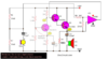
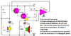
And you would have to have some resistor on the emitter two 25 ohms would work out nice there. Now if it was a tip31 and 32 a 2 ohm would work then move up to a bigger power transistor your getting to where a .20 or .22 ohm would do the job
These resistors are not 1/4 watt or haft watt tho there 5 watt in most amps
4533250.jpg

At some point both transistor will be on then if the speaker is not the path of lowest resistance the transistors become a short you pick a resistor to limit that short to range they can handle to get maxim power out the speaker.

Now for bad don't think bad applies here for a good amp for AM radio you probably looking to hear it LOL and if what hear is good enough to understand what your hearing guess thats
good enough for you as for me i hear lots of hissing sounds I want a little better amp.
 
Last edited:
I am aware of IEC standard where the minimal value starts with 1 ohm.
Your link clearly shows standard values but, look again, if you think no values below 1 are available because of that table, do you also believe no values greater than 10 are available?

That table actually shows the standard values within each DECADE of values. You can multiply those values by 0.01 or 1,000,000 to get any value you want.
 
I couln't help for it - I just couldn't got this linear/darlington thing out of my head, so I came up with this stupid idea of using an opamp instead of the common emitter stage, just for the sake of use the darlington pair. It's not supposed to be used for anything in practice (but would be fun if some of you guys had it for a test simulation).
 

Attachments

  • eleccircuit-com.png
    eleccircuit-com.png
    202.8 KB · Views: 136
At some point both transistor will be on then if the speaker is not the path of lowest resistance the transistors become a short you pick a resistor to limit that short to range they can handle to get maxim power out the speaker.
No, the amplifier output is class-AB that has a fairly low idle current of only about 3.6mA to avoid crossover distortion then its output transistors switch on separately for higher output currents. The upper NPN switches on for positive-going currents and the lower PNP switches on for negative-going currents.
 
I don't see any obvious distortions:
well, from this angle it looks like you have the beginning of ultrasonic oscillation, and the top half and bottom half are not symmetrical
using an opamp instead of the common emitter stage,
unfortunately, unless you reverse those op amp inputs, you get an oscillator
After I removed R8&R9, Ic current of Q4 is 320ma without any input, and both Q4 & Q3 are getting hot as hell. Just sitting at rest, Carl!
because you removed the resistors, you now have no local (local to the output transistors themselves) DC negative feedback in order to maintain control of the current, and you have also increased the base bias by removing the voltage drops across R8 and R9.
Tell me the truth please, do you seriously deep in your heart believe that this blurry tiny fragment of some exotic radio interception from 50 years ago - does it match you brave words '... Using four transistors (and less passive components) you can make a 'proper' push pull amplifier, as used in commercial radios etc. for decades'??? really?
This is just hilarious. I appreciate you efforts, though, it took you a whole day to dig out this piece of Roswell blueprints.
did you come here to learn or to troll????
 
unfortunately, unless you reverse those op amp inputs, you get an oscillator
I said it was a stupid one. Should be "fixed" now (is slightly less stupid)
 

Attachments

  • eleccircuit-com2.png
    eleccircuit-com2.png
    175.3 KB · Views: 128
Your opamp circuit will not work at all, because it has positive feedback instead of negative feedback.
The output stage is class-A with a high current all the time, and has severe distortion because its transistors strongly pulls upwards but the 20 ohm resistor weakly pushes downwards. A push-pull amplifier has a symmetrical output.
 

Attachments

  • non-working amplifier.png
    non-working amplifier.png
    95.7 KB · Views: 138
  • hopeless class-A amplifier.png
    hopeless class-A amplifier.png
    75.7 KB · Views: 144
Fixing the opamp to provide negative feedback will make no change to the weak pull-down by the 20 ohm resistor and the very high class-A idle current all the time.
 
did you come here to learn or to troll????
I am definitely not searching for apprenticeship from local gurus. So far I don't see anyone I'd be willing to learn from. (although I am open for offers).
I came here to get the correct and simple answers to my questions. Like, from a handbook, but with live index and online.
Instead I am mostly fed with contradicting advices with no logic and no understanding of what I really asked and what I am trying to achieve.
Like, I am trying to build simple amp for vintage AM radio, instead we talk about hi-fi components, non-existing distortions and I nearly burned my transistors following one particular advice from local 'guru'.
Another one keeps saying my circuit is ****, bragged he could do better and simpler, and finally gave me tiny blurry unreadable piece of picture from god knows where claiming this is the silver bullet.
Did I make it clear enough?
Now yet another simple question:
why the Ic at rest of this circuit is so huge (320 ma)?
My understanding is that when there is no input, both Q3 and Q4 must be almost closed. One of them opens when the input is on upper part of sine, another one opens on negative part. Can someone explain please?
 
No, the amplifier output is class-AB that has a fairly low idle current of only about 3.6mA to avoid crossover distortion then its output transistors switch on separately for higher output currents. The upper NPN switches on for positive-going currents and the lower PNP switches on for negative-going currents.
Is this by your simulation?
Care to explain why in reality idle current is 320 ma please?
 
I came here to get the correct and simple answers to my questions. Like, from a handbook, but with live index and online.
Have a look through this article, it explains or at least includes many of the design features and information others have already mentioned:

Some of the users on here are definitely "characters" to put it politely [and things tend to get sidetracked a lot], but there is also a vast amount of serious professional experience between the users and no one is giving fundamentally bad advice.
Thank you for the link, it looks useful.
NV_0803_Marston_Figure20.jpg

BTW similar circuit, no bootstrap, no negative feedback. Surgeon general should be mad at that Ray Marston :eek:

I was just thinking about the root cause of why this conversation ends up bad, well it looks like the approach 'like a handbook' does not work on forums.
Those who actually know, they don't care to waste time on a forums like that, those who is suffering from failed self-realization - they use such forums to feed on novices and satisfy their false pretenses.
Which leaves us books only, and good books are also not easy to find :(
 
Last edited:
I am definitely not searching for apprenticeship from local gurus. So far I don't see anyone I'd be willing to learn from. (although I am open for offers).
there have been some useful suggestions made here to improve the performance of your amplifier, but maybe the "delivery" could use some work... also, distrusting simulations isn't always the best tack either. for the most part, i have found that simulations with good part models will get you pretty close to how a circuit behaves in real life, usually within the ballpark of +/-5% to 10%, which for most circuits is close enough.
 
Stan, you built the 4 transistors amplifier and asked, " Why the Ic at rest of this circuit is so huge (320 ma)? and "Care to explain why in reality idle current is 320 ma please?".
The datasheets show that the typical forward voltage of a 1N4148 diode matches the Vbe of a 2N2222 transistor fairly well.
Simple math shows that the idle current is a little less than 1.9mA when the emitter resistors have been removed.
Then how did you get 320mA??
 

Attachments

  • driver and output stage of amplifier.png
    driver and output stage of amplifier.png
    97.7 KB · Views: 102
  • Vbe of 2N2222 transistor.png
    Vbe of 2N2222 transistor.png
    120.1 KB · Views: 95
  • 1N4148 vs 2N2222.png
    1N4148 vs 2N2222.png
    130.2 KB · Views: 117
I will try to find out. Maybe error in connections.
Yep, a shortcut there was. Breadboards, we love them. Idle is 6 mA now. A bit too much but at least by the order of magnitude matches your simulation. Apologies for my reproaches.
Summing up, I don't see any improvements worth of adding besides getting rid of R9&R10 which was quite obvious.
I'd expect Ic idle should depend on hFE, right? Which values did you enter in your simulation? My transistors are 200 (pnp) and 280 (npn)
 
Last edited:
Improvements:

A bootstrap capacitor, as someone mentioned early on in the thread.
Add a 100 Ohm resistor in series with R8 at the upper end and add a decent size electrolytic between the junction of the two resistors (+) and amp output (-).

That keeps the voltage across the lower resistor nearer constant as the signal voltage varies, which keeps the bias current through the diodes nearer constant and also allows a larger voltage swing in the output stage with lower distortion at higher levels, by maintaining the base current to the upper transistor rather than it dropping to zero as the base nears the positive supply voltage.

That's shown and explained in figure 13 of the link I posted.

Move the upper bias resistor of the first transistor from its own collector from its own collector to the amp output, as shown in many of the similar circuits in the link.

That's the "negative feedback" that helps improve linearity.


If you want to make it more powerful or have problems with the output transistors getting hot after a while for no apparent reason, make sure the bias diodes are thermally connected to the transistors.

Or add back low value emitter resistors and change to the adjustable bias circuit also mentioned early on, as detailed in figures 11 & 12 of the link article. With all those mods and a couple of extra transistors you can go from fractional watts audio out to several watts, as in fig. 16..
 
I am sure there is plenty of bells and whistles that could be added. Maybe your problem is you don't understand
that none of them are necessary. In any endeavor the main point is - know when to stop. Like, when you are making a log cabin in the middle of nowhere, you don't need an elevator or jacuzzi, although both can be built.. Savvy?
Next: I am planning to use this amp for AM radio, vintage style - transistors only.
Do I need a preamp or I can connect it directly to detector output? I am planning 2 transistors RF amplifier.
This is not a simulation question. This is not a theoretical question.
 
Last edited:
Thank you for the link, it looks useful.
View attachment 126036
BTW similar circuit, no bootstrap, no negative feedback. Surgeon general should be mad at that Ray Martson :eek:

I think you'll find that Ray Marsden never suggested that was a working or practical circuit, merely a demonstration towards making a practical circuit.

You might perhaps notice that 'circuit' has zero voltage gain?, plus the many other faults you've already identified.

You also might notice that it's not until figure 15, that he suggests 'practical amplifiers', which include bootstrapping and negative feedback (even if the feedback is a bit poor).
 
I think you'll find that Ray Marsden never suggested that was a working or practical circuit, merely a demonstration towards making a practical circuit.
Sorry, he forgot to share his suggestions with readers of 'Cookbook'. When I see a schematics _with_ components values, I reckon it is practical. When I see just designations, like, R1, C2, Q4 - then it is a theoretical explanation/demo. Simple, eh?
f.e, this is theoretical illustration:
NV_0104_Marston_Figure007.jpg

This is basic, but practical construction ( he even gives details of what type the capacitor must be):
NV_0803_Marston_Figure20.jpg


But I am not interested to waste time chatting on this counter-productive subject, I summarized already my acquired experience form this 'discussion': get rid of R9&R10, everything else is good enough for me.

And thank you for pointing it out, I misspelled his name in a hurry, I hate when this happens.
 
Last edited:
Status
Not open for further replies.

Latest threads

Back
Top