Continue to Site

Welcome to our site!

Electro Tech is an online community (with over 170,000 members) who enjoy talking about and building electronic circuits, projects and gadgets. To participate you need to register. Registration is free. Click here to register now.

  • Welcome to our site! Electro Tech is an online community (with over 170,000 members) who enjoy talking about and building electronic circuits, projects and gadgets. To participate you need to register. Registration is free. Click here to register now.

Display converting

Status
Not open for further replies.

omegatech

New Member
Hi all :)
A new guy checking in here. Looks like a nice forum and nice people - think I'll stick around for a while :D

I have a little headache regarding how I should solve this in a tidy manner so I'm asking you if you have any good advice.


I have an old radio with a VFD-display which is worn out. There is no way I can find a replacement display so I decided to build my own display with 7 (+1)-segment LED displays. There are 12 digits.

The logic behind this is a bit obscure (not hard, but why the H.. did they do it like this hehe).
The controlling logic is:
uPD8279C-5 for segment multiplexing
MC14515B for display multiplexing
(Output buffer for VFD consists of 3x uPA80C, -75V lines)

I'm connecting at the 5V side of the output drivers.

The case is:
1: The display select is a "low" output, the 11 others are "high" (thought it was the other way around before i made a test circuit).
2: Segment output is "high" when active.
3: I use common cathode displays.

The first experiment was using a NPN transistor for sinking the cathode when the display select was high. Bad result as I saw on a scope that it was the other way around :(
In the next attempt I used one more NPN transistor to make an inverter for the display select signal. It works okay, at least it seems to, but the display output is somewhat low, so I decided to buffer the segment output too, but that gives me a headache as the base voltage is too low when I have to pass it through a series resistor, LED and cathode sink transistor. It just won't light up properly. And on top of that, it requires too many transistors to be nice, 12+12+8 = 32 transistors :s (BTW: I'm using BC547C as they're cheap and reliable with a fairly high hFE).

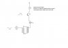
I will post a picture of the existing circuit when I get home.

Summary of the circuit and signals:
Matrix of 12 x 8 segment (7+ DP) LED common cathode
8 active high signals for segments
12 active low signals for displays

None of the circuits can sink or source a LED, I need buffers.


I hope this wasn't too confusing, so just ask if you're wondering about something.

Would appreciate any help available :)

PS: Getting parts here in Norway is a pain as we only have a couple of shops for electronics and they're via mail order (1-3 weeks delivery).
 
Hi,

Two things that may help -

The ULN2003 and ULN2803 range of drivers chips and the 7447 driver / decoder chip - both cheap and available.

Don't know the source of your display info and if those two chips are part of the existing circuit, but what is the possiblity of the source signal being input to a little pic chip so you can display onto a cheap 2 x16 lcd ?
 
Thanks Wp100,

The ULN series might be useful if I'm going to use an array of drivers for it, which all in all might be a good solution, but I have to draw it up and test virtually before I eventually order any IC's.

It might be possible to use a PIC or AVR to control a LCD, but I'm more old-school and have virtually no experience with such microprocessors. LCD's are dead cheap though :) It's all the stuff around the PIC/AVR I need to get going (software and hardware).

The outputs available to me is 8 lines of segment info multiplexed for 12 numbers (displays). Hooking up earlier in the circuit would be difficult as I won't get the data I need that easily there :(

If I had enough guts I'd rip out the whole controller logic and build my own from scratch, but it would require at least one large PIC or AVR. We're talking about a crazy amount of analog and digital inputs and outputs (the radio have tailored chips for that).
 
Hi,

I think it will be possible to do a seven segment display, but as you say it might take a lot more parts to get it right, although I'm not up to speed with all the latest transistor arrays, sure there must be a cheap package to suit.

Perhaps someone else in the forum can come in and help out ??

As for a micro / lcd - that would seem possible, think you are saying the 8 segment bits are coming out of the +5v uPD8279C-5 chip, so that is a Pic friendly signal, and I'm assuming ?, the 4 input lines to the 16 line decoder also come from uPD8279C-5.

If this is the case it would be a direct connection of the micro to your circuit.
A 2 x 16 lcd display routine is standard, its just a case of reading the segment bits for each change of the 4/16 dispay bits and a standard translation to the display. Can send a schematic if interested.
 
I'd like to help but I started with the likes of AVR's so I tend to avoid 7 segment display entirely, 2x16 or larger line displays are so cheap and easy to interface with I wouldn't even know where to start with the multiplexing alone. I also don't like multiplexing at all because I'm flicker sensitive. Regardless of frequency if you put two identical displays next to me, one fed with the exact same brightness only steady as the multiplexed one I'd be able to tell you which one was multiplex by moving my head no more than a few inches =) It doesn't give me headaches or anything but I notice it and it bugs me.
 
A simple circuit like this should work but for 12 segements thas a lot of chips.
 

Attachments

  • norwaytr.jpg
    norwaytr.jpg
    100.4 KB · Views: 143
Thanks for all the input guys, you're giving me some ideas :)

I'll check for available signals from the microprocessor to the drivers/multiplexers. Maybe use to control a PIC/AVR. A LCD would give me more options, and if I can hook up and find out more of the CPU I could also expand its functions (memory channels/presets for example).

Working too much these days so I can't fiddle with it as much as I would like to - I mean the radio of course :p
 
VFD displays usually last just about forever. But the high voltage drivers for them are pretty unreliable. I've fixed hundreds in old VCRs and returned them back to "super bright" (I find them annoyingly bright).

Have you tried fixing the display circuit as it stands? Quite often it is just one or more bad electro caps in the voltage driver. If you cherish the "old radio" that much to be worth major mods, then surely it's worth trying to keep it original? :)

I've never seen a VFD wear out, a few actually cracked/leaked but it's almost always the driver.
 
Actually, I haven't done anything the the original circuits since it looks like a display failure to me, but I will try to check it out. I don't have any voltages for reference, but what I measure now is about -75 volts from the high voltage driver. Some caps look a bit dark so I might try to change them just for "fun". What puzzles me is that the segments are half-on, well most of them at least. Looks like the multiplexed signal is "dirty" and is activating segments unintentionally.

I don't know too much about VFD's, but shouldn't I measure some voltage over the filament? I mean between the F and F pins on the display? I can only measure voltage on the filament relative to the grids or anodes. Looking at some web pages, they suggest upping the filament voltage.
Edit: The filament is glowing, I can see two small lines glowing faintly red.
 
Last edited:
I can't suggest voltages because they tent to be proprietary to the manufacturer and size of the display.

I wouldn't worry about the filament too much, the first thing to do is replace any electro caps. The voltage driver normally has a little inductor, the caps will be close to that and probably a couple of transistors near it. Replace the caps around that (they probably have bad ESR) and sometimes it's of the transistors failing but normally then you get no display rather than a dim display.
 
Hello smanches,

They would probably work if I make the correct converter for them and can fit them somewhere, but no, not as they are. The VFD I need is about 8 cm wide and 1 cm high (visible area), 12 characters and 8 segments per character. No drivers or anything - they are on the logic board in the radio.
 
I can't suggest voltages because they tent to be proprietary to the manufacturer and size of the display.

I wouldn't worry about the filament too much, the first thing to do is replace any electro caps. The voltage driver normally has a little inductor, the caps will be close to that and probably a couple of transistors near it. Replace the caps around that (they probably have bad ESR) and sometimes it's of the transistors failing but normally then you get no display rather than a dim display.

Thanks Mr RB, I will have a look at the caps there, it's easy to change them anyway.

I'm not sure if I can link to this with a new account, but I'll try anyway.
If you look at page 61, near the top, you see the display connector, the driver IC's and the HV driver. This might give you an idea about what I'm talking about. Seeing how the filament is connected at each side of the coil makes me wonder why I can't measure any filament voltage :confused:

Link to manual **broken link removed**
 
Update:

I tried to increase the filament voltage to see if anything got better, and yes, the display is brighter, but there's still a problem. The multiplexed segment signals are "leaking" into the other digits.

Example: If segment "a" is active on digit 1, it will light up segment "a" on digit 2, 3 and 6 - a bit dim though (not correct numbers, but as an example).

This could look like a driver/buffer issue, but I think it's from the logic side since I got the same result with my LED-version I started on.
Wonder if I can fix "dirty" logic signals :s Replacing the IC's is probably not possible as they're pretty outdated and impossible to buy anywhere.
 
Status
Not open for further replies.

Latest threads

New Articles From Microcontroller Tips

Back
Top