Electro Tech is an online community (with over 170,000 members) who enjoy talking about and building electronic circuits, projects and gadgets. To participate you need to register. Registration is free. Click here to register now.
Welcome to our site! Electro Tech is an online community (with over 170,000 members) who enjoy talking about and building electronic circuits, projects and gadgets. To participate you need to register. Registration is free. Click here to register now.
I have a diode in the supply line with a cap to ground after it (220uF) does this have an effective cut off frequency the same as a simple RC circuit would. Vs is 12v and the current is about 50 to 100ma.
If so are there any formulae to calculate the frequency?
Is this in a 12V DC application like in a car? What is the nature of the load? Is it a steady current draw, or it turning on/off?
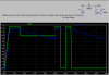
If this is an automotive application, then the diode prevents the capacitor from discharging backwards into the car's main bus during the times when the car's battery is pulled down during cranking. The capacitor charges to the normal battery voltage (12.6V) minus the forward drop of the diode (0.7V). If the battery voltage suddenly drops below 10V (i.e. during starting), the capacitor will discharge only due to the load current (100mA).
The rate of discharge can be calculated thus: Q = C*ΔV = I*t
Since the capacitor is initially charged to only 12.6-0.7 = 11.9V, it obviously can only supply 100mA for about t = C*ΔV/I = 220e-6*11.9/0.1 = 26ms until it completely discharges.
So, as a "filter", this thing is effective only for negative going spikes on the source side, and only for spikes lasting less than a few tens of us at that.
Absolutely brilliant. Thanks for the answer and the plot.
The only lasting query I have is that the diode has a small variation in voltage due to changes in current so this looks like an RC circuit but very small, does it in fact have any characteristics - even small that could be useful. Looking at the plot I suspect not but just have to ask?
It is a 12v car like circuit and the main power supply has lots of intermittent demands - not engine starting but lights, pumps, etc that can pull 20 or 30 amps from the supply - so are you suggesting a larger cap to stop these spikes and surges from coming through to the instrument circuit?
hi,
As Mikes image shows, heavy current demands on a battery will pull the 12Vnominal down, it could fall as low as 8v or 9V for a few tens of millsecs.
Any voltage sensitive circuit could be affected by this drop.
The series diode prevents the capacitor voltage from being pulled down by the same extent, also if any 'negative' spikes occurred on the battery wiring due inductive load switching, the diode would also block the spikes.
The value of the capacitor is chosen to suit the current drawn by the circuit and the expected duration of any 'voltage pull downs'
I would say that the resistive component of the diodes characteristic is not useful as an RC filter.
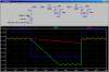
I have tried using this method to "filter" alternator whine. The alternator puts about 100mV p-p of AC on top of the battery voltage. Here I model it as a 1000Hz sine wave, although in real life it is really a three-phase, six-pulse full-wave rectified complex waveform. Note that at a 100mA load current, increasing the capacitor to 2200uF does a fair job of leveling the alternator ripple..., while the original 220uF doesn't attenuate the ripple much at all.
Hi Eric - The diode was initially put into the circuit to stop the capacitor from back feeding negative spikes on the battery side as you say and certainly stabilised the circuit's Vs, but it is mainly guess work.
Mike - thanks for the new plot and it certainly appears the diode/cap does act as an effective filter with the 2200uF in place.
So how to calculate its frequency. Just taking the equation for calculating ripple and looking at a 3dB drop in Vs ripple it gives f=2*I / (Vs*C) but that seems to be for sine input. To calculate what you simulated - a ripple on top of the DC eludes me and it is just that part that is of interest.
So if it does act as a filter then can a diode/cap followed by a diode/cap act like a network, surely it should and then we may be able to get 12dB/octave slope. That then leads onto - could it be made into an active 2nd order filter to minimise the voltage drop?
This site uses cookies to help personalise content, tailor your experience and to keep you logged in if you register.
By continuing to use this site, you are consenting to our use of cookies.