Continue to Site

Welcome to our site!

Electro Tech is an online community (with over 170,000 members) who enjoy talking about and building electronic circuits, projects and gadgets. To participate you need to register. Registration is free. Click here to register now.

  • Welcome to our site! Electro Tech is an online community (with over 170,000 members) who enjoy talking about and building electronic circuits, projects and gadgets. To participate you need to register. Registration is free. Click here to register now.

dimming LED strips

Status
Not open for further replies.

MrDEB

Well-Known Member
ran across this schematic and thinking of incorporating into my next sign PCB.
QUESTION maybe a 1K resistor before the gate to protect the gate?
Planning on using a smd pot
 

Attachments

  • dimming.jpg
    dimming.jpg
    35.4 KB · Views: 147
(Re)read post 14.

PWM output comes from a CCP peripheral... Capture, Compare, Pwm.

There are 2 of them, and CCP2 can be routed to one of two pins.
 
Maybe just put 2-7555 timers and associated circuitry along with MOSFETs.
then can adjust desired brightness without having to alter the PWM code.
Trying to make life easier.
 
The uC is controlling the automation of the proposed LED Neon sign I am looking to build. My first one for my town's centennial came out good but these LED Neon rope lights are really bright and thus have a dimming circuit.
I got to thinking about versatility thus why not add a dimming circuitry to 8 of the ports on the 18f2221 using 7555's.
The uC can still do its thing but being able to dim sections of the sign would IMO make a better-appearing sign.
 

Attachments

  • Screenshot (35).png
    Screenshot (35).png
    157.4 KB · Views: 125
Adding 8 copies of that is a lot of hardware to add when you've got a micro that could do the same thing with just a FET and some code, but then again you'd have to be able to write the code, so...

As I said, whatever floats your boat.
 
yes, I agree with you BUT reprogramming the pic to get the desired dimming effect for each LED strip is a concern.
I considered several options.
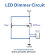
Need to look at whether to have the port pin supply the Vcc to the 7555 or use the 12v input that powers the LED strips.
As for hardware, 2-1n4148 diodes, 1- pot, 2- caps.
 
This part would give you 16 channels of PWM with just the two I2C pins from the uC. PCA9685

If you want pots to control the PWM value, just run the pots into ADC pins on the uC. Read those and send the values out to the PWM registers.
 
but these LED Neon rope lights are really bright

Don't you want all strips to be the same brightness? Doesn't sound like you need to constantly vary them. Use 1 PWM output, 1 FET and set the brightness of each strip by altering the series resistor.

Mike.
 
You haven't described the task in terms of specs for voltage, current, range, tolerances, sensitivity and reasons for this to make a good question that can be answered yet.
 
Have you guys never seen a MrDEB post before?????
 
My present sign I built has 8 MOSFETs to control the 8 different LED strips but I want to vary the brightness on several different channels. I have a short bit of code but it is not PWM. It varies the time the port pin is on. I need to reconnect the pickit, connect the computer, then plug in the 12 v supply. Load the reconfigured code and test.
If I have a dimming circuit for each of the 8 ports then I can adjust "on the fly".
Just thought it would make a better design.
 
this is what I am considering so each port has a dimmer circuit
the 7555 draws 300ua, well under the 20ma per port pin.
now to locate a 555 so I can experiment with it. Waiting for the 7555 from Ebay.
 

Attachments

  • Screenshot (36).png
    Screenshot (36).png
    156.3 KB · Views: 120
Status
Not open for further replies.

Latest threads

New Articles From Microcontroller Tips

Back
Top