Continue to Site

Welcome to our site!

Electro Tech is an online community (with over 170,000 members) who enjoy talking about and building electronic circuits, projects and gadgets. To participate you need to register. Registration is free. Click here to register now.

  • Welcome to our site! Electro Tech is an online community (with over 170,000 members) who enjoy talking about and building electronic circuits, projects and gadgets. To participate you need to register. Registration is free. Click here to register now.

Digitally controlled oscillator (DCO) design help required.

Status
Not open for further replies.
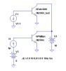
Qucs reports the model as

<_BJT Q2N3904_ 1 0 0 8 -26 0 0 "npn" 0 "1.4e-14" 0 "1" 0 "1" 0 "0.025" 0 "0" 0 "100" 0 "0" 0 "3e-13" 0 "1.5" 0 "0" 0 "2" 0 "300" 0 "7.5" 0 "0" 0 "0" 0 "2.4" 0 "0" 0 "0" 0 "4.5e-12" 0 "0.75" 0 "0.33" 0 "3.5e-12" 0 "0.75" 0 "0.33" 0 "1" 0 "0" 0 "0.75" 0 "0" 0 "0.5" 0 "4e-10" 0 "0" 0 "0" 0 "0" 0 "2.1e-08" 0 "26.85" 0 "9e-16" 0 "1" 0 "1" 0 "0" 0 "1" 0 "1" 0 "0" 0 "1.5" 0 "3" 0 "1.11" 0 "26.85" 0 "1" 0>
 
Last edited:
Code:
.model 2N3904 NPN(IS=1E-14 VAF=100 Bf=300 IKF=0.4 XTB=1.5 BR=4 CJC=4E-12 CJE=8E-12 RB=20 RC=0.1 RE=0.1 TR=250E-9 TF=350E-12 ITF=1 VTF=2 XTF=3 Vceo=40 Icrating=200m mfg=Philips)
 
You're welcome. I tried your Fairchild model in a couple of my old sims, and it worked fine.:confused:

Hi Roff,

I tried using my old 2n3904 model on your most recent sawtooth simulation (post timestamp 3:26AM) for "cyberheater" and the traces are not what I've expected. The transistor cannot fully turns ON to discharge the 22n capacitor so the integration ramp sometimes start from 6V instead of 3.2V

Perhaps you can try it too.
I just tried that sim. By changing the base resistor to 1k, and the base coupling cap to 2.2nF, it seems to work. It's interesting that the beta (Bf) on the Fairchild part (Bf=416.4) is higher than that of the Phillips part (Bf=300), yet on the simulated curve tracer (see attached), it is about half that of the Phillips transistor. It must have something to do with the other parameters.
There is a PNP in the .ASC file that I removed from the posted schematic, just to avoid the distraction.
 

Attachments

  • 2N3904 I-V curve tracer.PNG
    2N3904 I-V curve tracer.PNG
    7.7 KB · Views: 607
  • 2N3904 I-V curves.PNG
    2N3904 I-V curves.PNG
    8 KB · Views: 300
  • curve tracer bjt.asc
    1.2 KB · Views: 210
I just tried that sim. By changing the base resistor to 1k, and the base coupling cap to 2.2nF, it seems to work.

When I first looked at the traces, I immediately switched to use another transistor (2N2222) and the traces look neat. Therefore I know my 2N3904 model is somehow broken. I did go back to 2N3904 and increase the coupling cap to 3n3 and it also simulates better.

I asked for the model because I have remembered reading somewhere that the 2N3904 model has problem and somehow different models give better simulation performance under different applications.
It might be interesting to breadboard the circuit with both brands of transistors and see if either or both models are "broken". Furthermore, the model is typical, so a rigorous design with worst case beta would be imperative if this circuit was intended to be produced in volume. The transistor is really just a saturating switch, and the design should take this into account.
 
Roff,

Hi. I breadboarded the design but didn't have any 2n3904 transistors so substituted a BC108. I kinda got a strange looking ramp waveform but I'm sure it wasn't right.
I'm going to get hold of some 2n3904 after work tomorrow and try again.
 
Okay. I breadboarded it. ;)

**broken link removed**

And I got a nice looking ramp waveform :)
I'm outputting a 5v square wave from the arduino 1000hz and I'm using a potentiometer as a voltage divider to create my control voltage.

But I'm a bit confused why the output isn't higher. I'm using a power supply of +/- 12v and I was expecting an output swing close to that. I seem to be getting around 0.5v. Does that seem right. Apologies. I'm very new to this...

**broken link removed**
 
Last edited:
We need to see the schematic of what you built, including part numbers. Your ramp should have a positive slope. It looks like you are providing a control voltage greater than 3.2V. The control voltage goes from zero to 3.1V, as shown in the schematic. I probably need to provide you with a detailed schematic, instead of a simulation.
I thought you wanted to use a single supply. With dual supplies, it's a little simpler, conceptually, anyway.

I'm using this design (yours I think) with the same part numbers.

**broken link removed**

And yes. I'm using dual supplies. I figured it would be better in the long run.

One other thing. I'm taking the ground from the '+' leg of the opamp straight to ground and in your drawing you have a voltage source. Could that account for it?
 
Last edited:
I'm using this design (yours I think) with the same part numbers.

**broken link removed**

And yes. I'm using dual supplies. I figured it would be better in the long run.

One other thing. I'm taking the ground from the '+' leg of the opamp straight to ground and in your drawing you have a voltage source. Could that account for it?
With ground on Vin+, you will have to have a negative control voltage, which sends you back to your original circuit.
The 3.2V in my single-supply circuit does not have to be a battery or a power supply. If you decide to pursue the single-supply version, let me know and I can draw up something that should work.

Wait. Are you saying that the '+' side of the opamp should have gone to the negative rail instead of ground?
 
Wait. Are you saying that the '+' side of the opamp should have gone to the negative rail instead of ground?
No. I am confused about what you have. You need to post a schematic.

I am saying that, with a single supply, the +input has to connect to 3.2V, and the control voltage goes from 0V to 3.1V.
With the dual supplies, you can connect the +input to GND, but you will need the inverting unity-gain amp between your control voltage and the integrating op amp, which you have in your original circuit. I think it will work OK. All the stuff I designed was so you could use a single supply, you turkey!:D
 
All the stuff I designed was so you could use a single supply, you turkey!:D

Ha ha.

No. I'm most definitely using a dual supply. It's amazing I got a waveform out of it at all.

Tomorrow I'll breadboard again and add the inverting unity gain opamp as I had in my original design.

Thanks once again for your help. It's very appreciated. :)
 
You might want to try this. It still uses a dual op amp, but you get a buffered output, with the sawtooth centered around zero volts. It works well in simulation.
 

Attachments

  • sawtooth gen dual supply sch.PNG
    sawtooth gen dual supply sch.PNG
    21.7 KB · Views: 460
Hello,

I resurect this post, because I want to give a try to an arduino DCO... The problem is, I'm really not knowledgeable with electronics, so I apologize in advance for dumb thoughts.

I tried to replicate Ron's design in the previous post, but by replacing some parts with the parts I own: the op-amp is an LM324, and the transistor a BC547. I could not get the same power supply icon with last LTSpice, I hope the replacement are ok.
I tried to simulate the circuit, but I do not get a ramp for 'out'.

2 other things:
- I could not upload the file for LM324 on the forum, sorry, it's here: https://www.google.com/url?sa=t&sou...qIznMJ_Xg&sig2=PGJLsmXbVp3sJUWY2-R9AA&cad=rja

- I want the final schematics to use a single supply, no +12v or -12v, only the arduino power supply. I tried Ron's design first to replicate a working design, and to familiarize myself with ltspice... no chance though...

Is there someone kind enough to inspect the file, and spot any errors ?

best regards,

stephane
 

Attachments

  • DCO.asc
    2.4 KB · Views: 188
Can I ask, what is TH and TL in the OP's calculation? I get the same value as him when I work out the half period? thank you
 
Status
Not open for further replies.

New Articles From Microcontroller Tips

Back
Top