Continue to Site

Welcome to our site!

Electro Tech is an online community (with over 170,000 members) who enjoy talking about and building electronic circuits, projects and gadgets. To participate you need to register. Registration is free. Click here to register now.

  • Welcome to our site! Electro Tech is an online community (with over 170,000 members) who enjoy talking about and building electronic circuits, projects and gadgets. To participate you need to register. Registration is free. Click here to register now.

Digitally controlled oscillator (DCO) design help required.

Status
Not open for further replies.

cyberheater

New Member
It's been a long while since I've dabbled in electronics and I need your help to critic this schematic I designed.

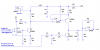
I am trying to design a digitally controlled analogue oscillator. The idea is that a control voltage is generated by the a microcontroller (Arduino) which is used via the 2 op amps, resistor and capacitor network which forms a integrator circuit.

The microcontroller will also send out a squarewave (top left) at the desired frequency which gets converted eventually via the transistor and shorts the ramp voltage to ground. This forms the sawtooth circuit.

Does this design seem reasonable. Thanks.

**broken link removed**

The note values i've calculated are these:-

**broken link removed**
 
Last edited:
That's technically not an oscillator, it's a sawtooth generator. An oscillator is autonomous (no external input), and free-runs by virtue of positive feedback.
You don't need the 1Meg resistor. It just makes your ramp slightly nonlinear. You will have to adjust your values slightly if you want to omit it and still get exactly 9.5V peak.
I assume you know you will need positive and negative supply voltages.
I ran a simulation on LTspice, and it does make a nice sawtooth. Why do you want a sawtooth wave at various musical note frequencies?
 
Ron,

Thanks for taking the time to look at this.

Yes, it's not a true oscillator. I'm trying to design a digital oscillator for a music synthesizer. The outputs will eventually be ramp (sawtooth) and squarewave. I did not want to go down the stand voltage controlled oscillator because of frequency drifting due to temperature changes etc...

You say that I would have to run this off + and - supply rails. What would I have to do convert the design to run off a single supply?

Thanks for your help.
 
It would be easier to use a simple VCO fed by a DAC. The 565 is a PLL that has an easy to use VCO in it.
 
It would be easier to use a simple VCO fed by a DAC. The 565 is a PLL that has an easy to use VCO in it.
The VCO will drift unless it is in a PLL. That's the reason he is using the Arduino for frequency generation.
 
You say that I would have to run this off + and - supply rails. What would I have to do convert the design to run off a single supply?

Thanks for your help.
How do you plan to control the voltage keeps the amplitude constant?
 
How do you plan to control the voltage keeps the amplitude constant?

I'm going to get the microprocessor to send out a PWM and then filter it to create a control voltage. I've simulated that by the battery you see in the bottom left (0.6v). You can see the output control values i've calculated in the spreadsheet.
 
Last edited:
Are you going to AC-couple the output of your sawtooth generator? The reason I ask is that a single-supply op amp, even with rail-to-rail output, can only get within ≈100mV of zero volts. If you AC-couple, I suppose that won't matter.
I can show you how to do it with a single supply, but if I post the schematic, On1aag will come up with something with half as many parts, and compare me to Rube Goldberg again.:D
 
I can show you how to do it with a single supply, but if I post the schematic, On1aag will come up with something with half as many parts, and compare me to Rube Goldberg again.:D

Please. Any input would be appreciated. I've got quite a few quad single supply opamps so I would like to put them to some use.
 
Please. Any input would be appreciated. I've got quite a few quad single supply opamps so I would like to put them to some use.
What kind of single-supply, rail-to-rail I/O op amps do you have? I would like to look at the specs, and maybe run some simulations before I post a circuit that will disappoint you if your op amp is not up to the task.
 
Are you going to AC-couple the output of your sawtooth generator? The reason I ask is that a single-supply op amp, even with rail-to-rail output, can only get within ≈100mV of zero volts. If you AC-couple, I suppose that won't matter.
I can show you how to do it with a single supply, but if I post the schematic, On1aag will come up with something with half as many parts, and compare me to Rube Goldberg again.:D


:D:D:D:D

I know how you feel, but it's all in a good cause. Consider it kind of an open source forum with lots of peer review. :p

Lefty
 
What kind of single-supply, rail-to-rail I/O op amps do you have? I would like to look at the specs, and maybe run some simulations before I post a circuit that will disappoint you if your op amp is not up to the task.

These are LM324N. Thanks.
 
what you can do is to use the pwm to charge a cap through a resistor and discharge once it gets to a particular voltage. the ramp would not be perfect and the frequency would be value dependent but the ramp peak (volume) would be fixed instead of varying with frequency.
 
These are LM324N. Thanks.
Well, It's not a very good op amp, but the attached circuit works in simulation. Due to the finite slew time when the ramp resets, doubling the amplitude control voltage with each doubling of frequency will not quite keep the amplitude constant. You may have to use a lookup table for the PWM duty cycle. A faster slewing op amp would allow you to use a shorter reset pulse (lower value for C2), which would reduce but not eliminate the slewing problem.
The unused op amp section is tied to +10V because it's a convenient voltage within the input common mode range of the op amp.
If you are making multiple units, you might need to add a pot to calibrate the output amplitude. If so, let me know.
U1a can double as the op amp in a 2 or 3 pole lowpass filter for your PWM if you need it. Let us know if you want to do that. We will need to know the PWM frequency, and how much residual ripple you can tolerate on the control voltage.
 

Attachments

  • sawtooth generator.PNG
    sawtooth generator.PNG
    33.1 KB · Views: 1,049
Last edited:
what you can do is to use the pwm to charge a cap through a resistor and discharge once it gets to a particular voltage. the ramp would not be perfect and the frequency would be value dependent but the ramp peak (volume) would be fixed instead of varying with frequency.

I think i'm kinda doing that with my current design. At least I hope so.
 
Well, It's not a very good op amp, but the attached circuit works in simulation. Due to the finite slew time when the ramp resets, doubling the amplitude control voltage with each doubling of frequency will not quite keep the amplitude constant. You may have to use a lookup table for the PWM duty cycle. A faster slewing op amp would allow you to use a shorter reset pulse (lower value for C2), which would reduce but not eliminate the slewing problem.
The unused op amp section is tied to +10V because it's a convenient voltage within the input common mode range of the op amp.
If you are making multiple units, you might need to add a pot to calibrate the output amplitude. If so, let me know.
U1a can double as the op amp in a 2 or 3 pole lowpass filter for your PWM if you need it. Let us know if you want to do that. We will need to know the PWM frequency, and how much residual ripple you can tolerate on the control voltage.

Roff. Thank you very much for taking the time to look at this. I've took your feedback about the slew issues on the LM324N. So would a jfet opamp like the TL081 be a better choice.
Also. I've decided that I'm going to have to go down the positive and negative supply route. Probably will supply with +/- 15v. Is that a better choice. Does that simplify the circuit.
TL074 or TL084 are much better quads, but their outputs only swing within 3V of the supply rails. You didn't answer the question about AC-coupling the output. If you are going to, then that isn't an issue, although if you want 9.5V p-p, you will need a single 15V supply, and a few circuit modifications
 
Here is a takeoff on your original circuit that uses a TL072, and should work if you can AC-couple the output (which you never addressed). It is straight off my simulation, so it needs to be cleaned up before you can build it.
 

Attachments

  • AC-coupled sawtooth gen.PNG
    AC-coupled sawtooth gen.PNG
    20.7 KB · Views: 716
Here is a takeoff on your original circuit that uses a TL072, and should work if you can AC-couple the output (which you never addressed). It is straight off my simulation, so it needs to be cleaned up before you can build it.

Roff, Thanks. I tried to get on the forum again last night but kept getting a timeout.

Yes. I do intend to AC - couple the output.

I'm going to breadboard the design at the weekend and let you know how I get on.
 
Hi Roff,

My 2n3904 model is broken and the simulated traces look bad. I tried many models from the internet and they are all with the same parameter values as what I've.

Can you post the 2n3904 bjt model?

Code:
.MODEL 2N3904 NPN(Is=6.734f Xti=3 Eg=1.11 Vaf=74.03 Bf=416.4 
+   Ne=1.259 Ise=6.734f Ikf=66.78m Xtb=1.5 Br=.7371 Nc=2 Isc=0 
+   Ikr=0 Rc=1 Cjc=3.638p Mjc=.3085 Vjc=.75 Fc=.5  Cje=4.493p 
+   Mje=.2593 Vje=.75 Tr=239.5n Tf=301.2p Itf=.4 Vtf=4 Xtf=2 Rb=10 
+   VCEO=40 ICRATING=200M mfg=Fairchild)
 
Status
Not open for further replies.

Latest threads

New Articles From Microcontroller Tips

Back
Top