Continue to Site

Welcome to our site!

Electro Tech is an online community (with over 170,000 members) who enjoy talking about and building electronic circuits, projects and gadgets. To participate you need to register. Registration is free. Click here to register now.

  • Welcome to our site! Electro Tech is an online community (with over 170,000 members) who enjoy talking about and building electronic circuits, projects and gadgets. To participate you need to register. Registration is free. Click here to register now.

digital clock circuit

Status
Not open for further replies.

obnikon

New Member
Hi you all,
I learn Electronics at school and I found it very intersting.
I decided to improve my skills so I took on myself a nice project.

Building a digital clock.
How ever , I dont want to use ready chips.
Only the basic compontes: Flip Flops,gates,decoders and Pulse Generators.
Therfore there werent post that might helped me, all of them are contain
kind of uknown compontes (to me).


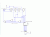
As a start I tought how to manage the first numeral seconds:
(Units of Seconds (0))

4 T FF
all the T inputs will get +Vcc.
Decoder BCD to 7SEG


So please take a look at the picture that attached to the post
and tell me if its right and how can I now connect it to the Ten Seconds(10).
i know that when the "Q"'s value is 1010 I need to do a reset to the
Units Seconds and add a pulse to the Ten seconds - but I dont know
how....

Please help by adding your circuits too.
Thanks!!

Thanks.
 

Attachments

  • try1cir.GIF
    try1cir.GIF
    15.5 KB · Views: 3,624
Yeah Cheezzzzzzzz

You can do the trick like this.. Circuit attached..
I have attached ZIP file containing the Circuit Maker file...Just open the file in circuit maker.

You can reset on desired position using AND gate.

**broken link removed**
Hope it will help.

Ur project is going to coastly...

Muhamad Ahmed.
 

Attachments

  • Clock.zip
    2 KB · Views: 2,410
You can replace it with flip flops and gates. The 4024 data sheet contains the complete circuit diagram.

Or google for "ripple counter".
 
Great , Thank you very much.
I found the data sheet and it is contain the diagram :)

Can you help me a little bit and now show me how to connect the
seconds to minuts?

And another question,
why you connected the Output wire of U5A to the U1 MR and to the U3 CP ?

Thanks.
 
Last edited:
From some reason the button of "edit" dissapear :confused:

So, after lot of work I successed in doing the Seconds and Minutes.
Now I have some problems with handling a 24 Hours.
As you can see:
01 11 21
02 12 22
03 13 23
04 14
05 15
06 16
07 17
08 18
09 19
10 20


As you can see the Units of the HOURS is used in different times.
for example: 01,11,21 - they have the same Hours Unit
so how can I know for sure when its 01 and when its 11 and when 21
and the same to 02,12,22 and to 03,13,23 ?

My guess is to check if the Tens Hours is equal 0
if TRUE and the Units Hours equal to 10 (Not really equal) then:
Reset Unites Hours
ADD PULSE to Tens Hours

and the same in case of 1X and 2X.
Am I right?
 
If the edit button doesn't show up on one of your posts simply click on the Refresh button in your browser and it should show back up. Happens to me all the time right after I make a post (I'm a serial editor =>)
 
well narendrababu, we cant just give you everything! you have to search the web a little bit and actually do some work. We cant do all the work while you reap the profits!
 
obnikon said:
Great , Thank you very much.
I found the data sheet and it is contain the diagram :)

Q no 1:Can you help me a little bit and now show me how to connect the
seconds to minuts?

Q no 2:And another question,
why you connected the Output wire of U5A to the U1 MR and to the U3 CP ?

Thanks.

Answer of ur first question,
Make the same circuit as u have made for the Seconds and Divide ur Clock cycle with 60(u can use two or three Johnson Counter) and connect the output of the divider circuit with the circuit(CP) u have made for minutes.

Answer of ur second question,
For example u want to apply a condition. What will u use for it!!! U can use and gate.. We want that after the 9 there should be zero. At the position of 10 we connect the AND gate and it's output is connected with MR(of U1) and CP(of U3)..
Now how it works,
As the 10th pulse reaches at the U1 it will convert this input into binarray. it's output will be "0101" now AND gate will perform it's action it will makes it's output High because both of it's input are High. AND's gatte out will reset the U1 to Zero. And the Same time it will incriment into the 10's digit of Second..

Hope this will help.
My Poor English:(
 
Great,
Is there any replacement for the Output wire of U5A to the U3 CP ?
Ive been told that this wire doesnt allways works.
 
self correcting digital clock

hellow guys can anyone give me idea on how to design a self correcting digital clock.what it does is that it should be able to correct itself automaticaly by looking at its reference points wheather its GPS or whatever.help me guys!!!!
 
hellow guys can anyone give me idea on how to design a self correcting digital clock.what it does is that it should be able to correct itself automaticaly by looking at its reference points wheather its GPS or whatever.help me guys!!!!

hi,
Whats your location.???
 
Status
Not open for further replies.

Latest threads

New Articles From Microcontroller Tips

Back
Top