Dr.EM
New Member
I've been reading about digital amplifiers, and have a small idea of how they work now. I was thinking, arn't they ideal for subwoofers? The dynamic range isn't so vital for subwoofers, and your going to be filtering the high frequency signals either way. Also, it allows for a higher power in a smaller space without the need for such excessive heatsinks.
Is it actually possible to design a digital amp as a project, without buying the highly specialised ready made chips? They are all surface mount anyway by the looks of it.
Is it actually possible to design a digital amp as a project, without buying the highly specialised ready made chips? They are all surface mount anyway by the looks of it.
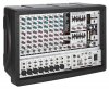
 , very compact for that sort of power yeah.