Continue to Site

Welcome to our site!

Electro Tech is an online community (with over 170,000 members) who enjoy talking about and building electronic circuits, projects and gadgets. To participate you need to register. Registration is free. Click here to register now.

  • Welcome to our site! Electro Tech is an online community (with over 170,000 members) who enjoy talking about and building electronic circuits, projects and gadgets. To participate you need to register. Registration is free. Click here to register now.

differential signal

Status
Not open for further replies.
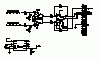
That might work. If you are lowpass filtering the PWM prior to going to the op amp, you should put the same filter on +5V. If you are not filtering the PWM, you will need to pay attention to op amp bandwidth and slew rate.

Yes, i am lp filtering the pwm, i do this in order to get the "analog" signal. For the sake of my education, why should i put the same filter on the +5?
 
jnnewton said:
Yes, i am lp filtering the pwm, i do this in order to get the "analog" signal. For the sake of my education, why should i put the same filter on the +5?
Filters have delay. Unless you put the same delay in the +5 path, your motor will jump on power up.
Actually, a better solution might be as below. Hold both inputs at zero until you want the motor to start.
You can alternately use 5V without PWM on the other input, as you suggested. Filter it identically to the PWM.
If the motor still twitches, we should be able to come up with an enable. You would need to post a fairly complete schematic.

EDIT: Oops, this still has +/-10V outputs .
 

Attachments

  • single-ended to diff sch1.PNG
    single-ended to diff sch1.PNG
    17.1 KB · Views: 125
Hi all,

I built the attached circuit, but can only get the outputs to swing from 4.9 V to -2.47 V (approximately) and need them to go from -5 to 5. This will give me the 0-10V i need. What do you think could be the issue. Also, by using the complement of the pwm output, the motor doesn't jump at startup. Also at the point where the differential signal is 0 V, the two outputs show 1.14V with respect to ground. Shouldn't this be zero with the circuit I have? Finally the -12 V bus generated with the switched capacitor is only giving 10.08 V when on, can anyone suggest a different setup to get a little more margin for the differential op amp?
 

Attachments

  • PWM Circuit.gif
    PWM Circuit.gif
    19.4 KB · Views: 115
The input voltage of the MCP602 can only handle (Vcc-1.2) on the high side. The output swings (almost) rail-to-rail, with no load. You have a very heavy load on both amplifiers, so the output swing will be reduced.
You don't need that high-speed diff amp. Why don't you do it like this?
TL074 is 4 op amps in one package. I show power supply pins on each amplifier, but this is just for simulation purposes.
 

Attachments

  • PWM amp.asc
    3.9 KB · Views: 108
  • PWM amp.PNG
    PWM amp.PNG
    31.7 KB · Views: 114
Status
Not open for further replies.

Latest threads

New Articles From Microcontroller Tips

Back
Top