I am creating a differential analog signal from the pwm of a dspic30f microcontroller. I have filtered the pwm signal and get a nice analog output using a simple r/c filter. The next step is to get a +/-10V signal from my 0-5V output. I have a couple of ideas and thoughts about how to do this. Any suggestions or comments would be greatly appreciated.
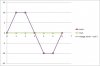
1. Use the single pwm output into an op amp with basically a 2.5V offset. This way the op amp output is 0 when the pwm is at 50%.
A. The drawback i see to this is if the pwm, for whatever reason doesn't come on or stops, the op amp output will go to -2.5 Volts.
1. A solution to this might be to run the op amp output through a switch, so that if the controller quits, the switch opens and the output falls back to zero.
B. Another drawback is startup where the pwm starts at zero, there would be a bit of time that will leave the output at -2.5V. This could also be solved by a switch at the output of the op am.
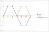
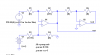
2. I like this one better: use two pwm channels and drive a fully differential op amp with them. If ch 1 is at 100% duty cycle, 2 at 0% , the input to the amp is 5V, If ch 2 is at 100% and 1 at 0%, the input to the amp is -5V.
A. The drawback is the use of two channels, and the synchronization of the two in software, and possibly the crossing over the zero point.
Please let me know your thoughts on the matter
1. Use the single pwm output into an op amp with basically a 2.5V offset. This way the op amp output is 0 when the pwm is at 50%.
A. The drawback i see to this is if the pwm, for whatever reason doesn't come on or stops, the op amp output will go to -2.5 Volts.
1. A solution to this might be to run the op amp output through a switch, so that if the controller quits, the switch opens and the output falls back to zero.
B. Another drawback is startup where the pwm starts at zero, there would be a bit of time that will leave the output at -2.5V. This could also be solved by a switch at the output of the op am.
2. I like this one better: use two pwm channels and drive a fully differential op amp with them. If ch 1 is at 100% duty cycle, 2 at 0% , the input to the amp is 5V, If ch 2 is at 100% and 1 at 0%, the input to the amp is -5V.
A. The drawback is the use of two channels, and the synchronization of the two in software, and possibly the crossing over the zero point.
Please let me know your thoughts on the matter