Continue to Site

Welcome to our site!

Electro Tech is an online community (with over 170,000 members) who enjoy talking about and building electronic circuits, projects and gadgets. To participate you need to register. Registration is free. Click here to register now.

  • Welcome to our site! Electro Tech is an online community (with over 170,000 members) who enjoy talking about and building electronic circuits, projects and gadgets. To participate you need to register. Registration is free. Click here to register now.

Did I learn?

Status
Not open for further replies.

mike_ss

New Member
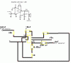
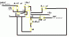
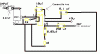
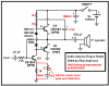
Hi, I have been having problems reading schematics, but I think I am getting the hang of it now. Can you please take a look at the schematic and see if I have everything connected correctly? I used Express PCB to make a dummy model of what I would put on a breadboard. (Its not how I would put it on a PCB, just to see if I connected everything correctly) Also can you tell me what I sould do for pin #7 where there is the dotted line, a capacitor, then ground. Thanks a lot!
 

Attachments

  • post_gif_.gif
    post_gif_.gif
    8.8 KB · Views: 864
There are several errors.
The 10 k resistor on the input should be a 10 k pot as shown on your circuit.
There should be a 4k7 resistor between pin 2 and the track you labelled as - , ie. gnd.

The cap connected to pin 7 should be 0.1 uF according to the data I have. They also state that it is optional.

There should be a 0.47 cap in series with the pot at the input.

I would also add a 10 uF bypass cap between pin 6 and gnd
 
Thanks for the help! Does this look better? I appreciate all of the input!
 

Attachments

  • post2_685.gif
    post2_685.gif
    5.8 KB · Views: 771
Here's the answer to ljcox's suggestions, and change the obvious 4K to 4.7K.
 

Attachments

  • ckt_108.gif
    ckt_108.gif
    5.1 KB · Views: 753
I agree with mstechca's corrections. The 10 k pot has 3 pins as mstechca has shown. You were showing it as a resistor. But it is a potentiometer.

Also, you have not included the 10 uF bypass cap that I mentioned.
 
I thank you guys for the help. I'm gonna try and build it now and see if it works. What exactly does the 10 uf bypass cap do? Thanks again.
 
A bypass capacitor is supposed to make your battery last longer. Think of it as a secondary battery.

Also, I heard that it helps regulate voltage. Correct me if that is wrong.

Nigel makes bypass capacitors a requirement when he shows circuits.
 
A 0.1uF to 10uF supply bypass capacitor provides a high frequency low impedance for the power supply to keep the amplifier from oscillating at a high frequency. A bypass capacitor with 470uF to 1000uF holds up the supply voltage when the internal resistance increases of a battery running down.
All IC circuits need a supply bypass capacitor.

The LM386 has an input bias current of only 0.25uA so a 4.7k resistor isn't needed at pin 2. The manufacturer shows pin 2 connected to ground.

A 47uF capacitor from pin 7 to ground reduces output hum from full-wave-rectified power supply ripple 150 times. Any more than 47uF doesn't make any difference.
 
Will the circuit work fine without the bypass capacitor? Theoretically can you connect the input of another amplifier circuit to the output of that circuit to make the amplification even greater? (look at the attached picture) Thanks
 

Attachments

  • post_170.gif
    post_170.gif
    7.5 KB · Views: 731
The 1st LM386 has a gain of 200 and is designed to drive a speaker, not a volume control. It has some noise output. The 2nd LM386 amplifies the noise from the 1st one 20 times. The output will be HISSSSSSS.
If you need a high-gain preamp then use a low-noise audio opamp.
Why do you need so much gain?

The 250uF capacitor coupling the 1st amp to the second has a high value for driving an 8 ohm speaker. Only about 0.1uF is needed to drive the 10k volume control.

Your circuit doesn't have a supply bypass capacitor so both ICs will probably oscillate at a high frequency.

The "bypass" capacitors in your circuit are to reduce mains hum. If your supply doesn't have ripple then they aren't needed.
 
Thanks audioguru. I am just trying to learn and didn't know they worked like that. I'm still going to try and build the first one. What exactly is 'gain'? If you hook up say a CD player to a speaker, then a CD player through the amp to the speaker would it sound better then? Thanks again.
 
mike_ss said:
Thanks audioguru. I am just trying to learn and didn't know they worked like that. I'm still going to try and build the first one. What exactly is 'gain'? If you hook up say a CD player to a speaker, then a CD player through the amp to the speaker would it sound better then? Thanks again.

'Gain' is how many times it amplifies - but there are essentially two types, voltage gain, and power gain. Generally a preamp gives voltage gain, and a power amp gives voltage gain AND power gain.

If you connect a CD player to a speaker you will get next to nothing, the voltage output is low, and the power output is even lower, far too low to feed a speaker.
 
mike_ss said:
If you hook up say a CD player to a speaker, then a CD player through the amp to the speaker would it sound better then?
If the CD player is a portable one that is designed for earphones, then two LM386 little amps for stereo will play speakers not very loud, they are only 0.5W each with a 9V supply.
If the CD player already has a stereo power amp in it then adding a pair of little LM386 amps for stereo will sound much worse.
 
and get rid of RL that is connected in parallel with your speaker or you are asking to drain the battery some more, if RL is low enough (< 8 ohms).
 
mstechca said:
and get rid of RL that is connected in parallel with your speaker or you are asking to drain the battery some more, if RL is low enough (< 8 ohms).
RL is the heater that keeps it nice and warm. :lol:
 
audioguru said:
RL is the heater that keeps it nice and warm. :lol:
you are so funny! :lol:
Thats true, especially if RL is too low in wattage rating.
 
Does anybody have any relatively simple circuits that would have enough power to drive speakers? Or is it more complex than I think? Thanks.
 
mike_ss said:
Does anybody have any relatively simple circuits that would have enough power to drive speakers? Or is it more complex than I think?
You had an LM386 IC power amplifier simple circuit that is designed to drive a speaker. Its max output power is only 0.5W.
You can buy other power amplifier ICs that are nearly as simple but provide more power. It isn't complex to determine how much power you need. Hint: ten times the power sounds only twice as loud.

Then you need a power supply for the amplifier.
 
mike_ss said:
Does anybody have any relatively simple circuits that would have enough power to drive speakers? Or is it more complex than I think? Thanks.

It depends on how you want to build it. Harry's homebrew homepages has a section on audio amplifiers in his transistor biasing section (under reference, and building blocks I think).

What he shows is a transistor version of a power amplifier, and it works quite nicely! In fact, it worked so nicely even under stressful conditions, that audioguru recommended that I omitted the 22 ohm resistor between the PNP's collector and ground!
 
MStechca,
An LM386 produces 0.5W with 0.2% distortion. It has about 20 transistors and costs $1.19 in Canada.
Your amplifier produces 0.3W with very high distortion. Its 3 transistors total cost is $.48 in Canada. Adding a resistor and a capacitor to bootstrap it and another diode will reduce its 40% distortion to 4%, and increase its power to 0.4W.
 

Attachments

  • simple_amp_626.png
    simple_amp_626.png
    14.5 KB · Views: 466
Status
Not open for further replies.

Latest threads

Back
Top